| Update : may 19th, 2018 |
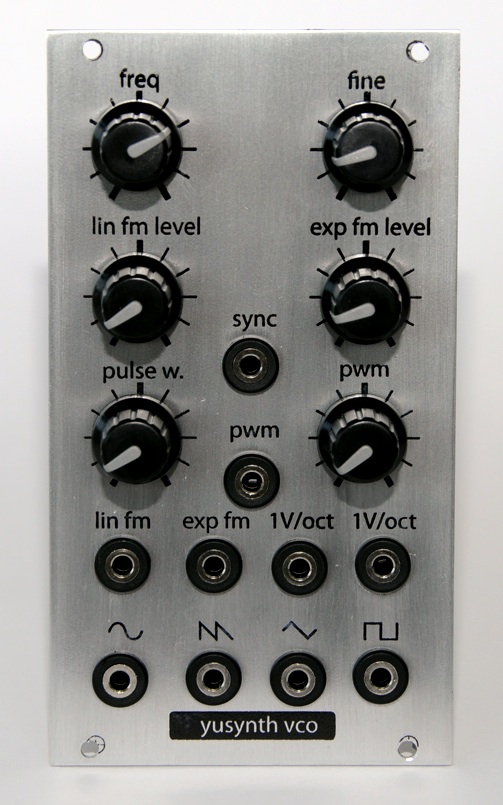
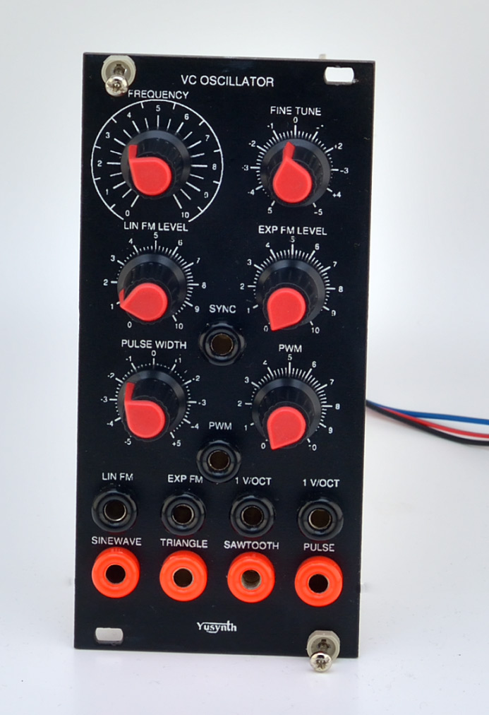
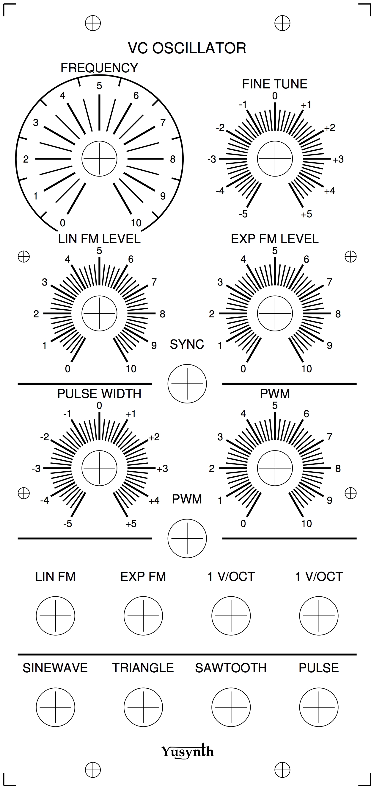
VCO
|
En français
 |
 |
back to summary |
 |
 |
| Description |
| Update : may 19th, 2018 |
VCO
|
En français
|
|
back to summary |
|
|
| Description |
|
|
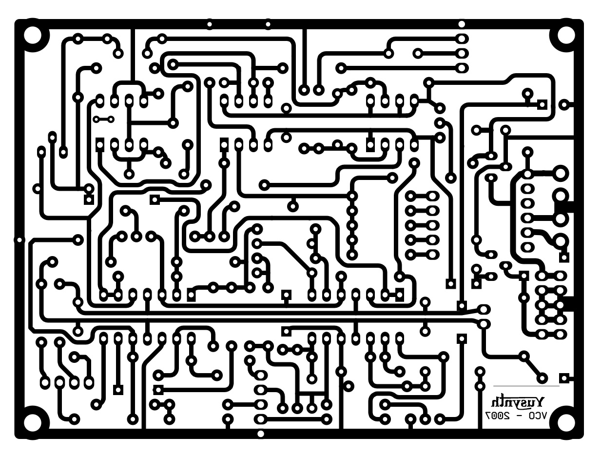
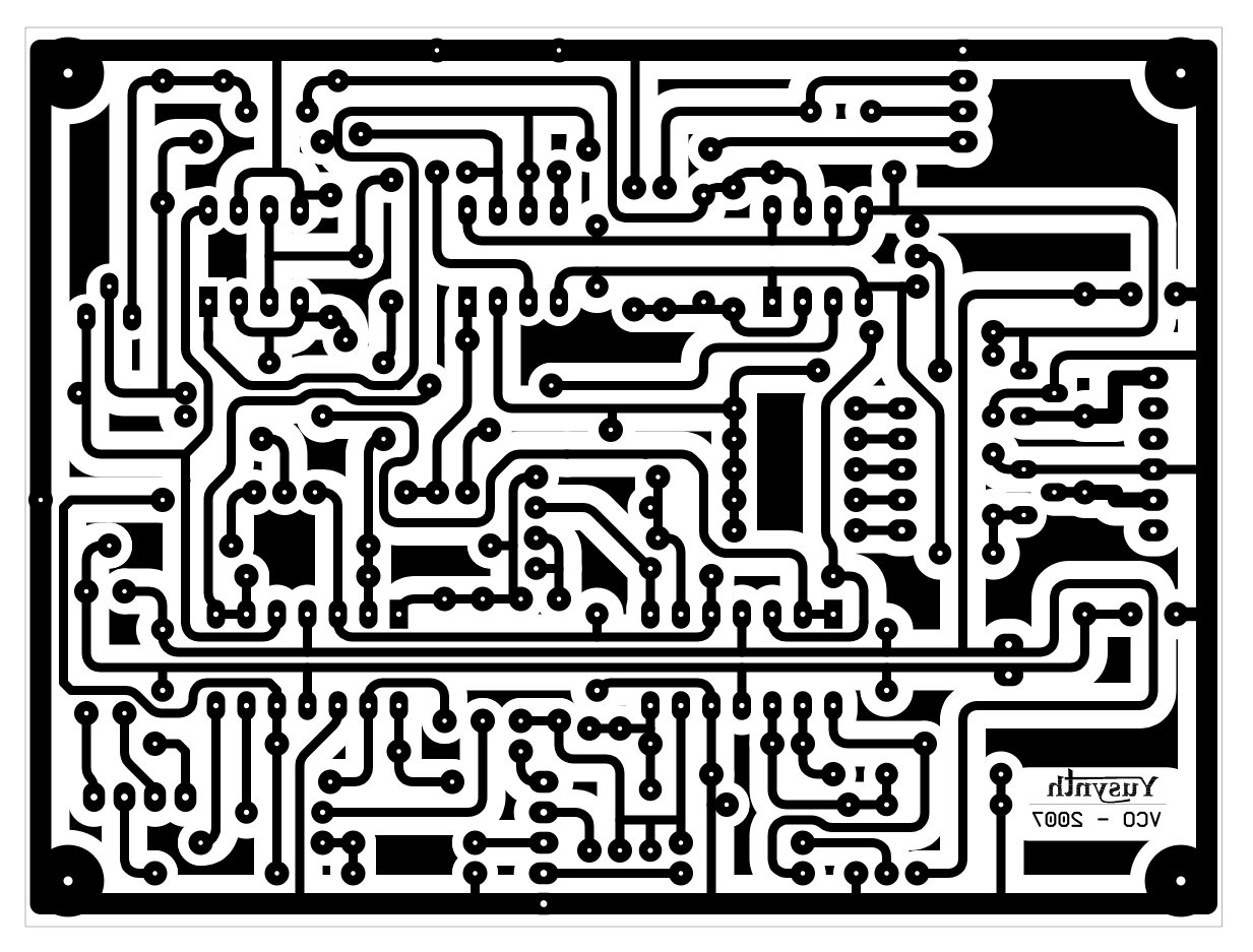
|
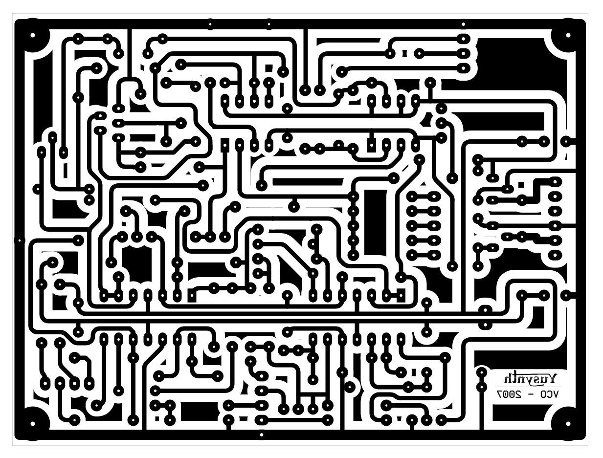
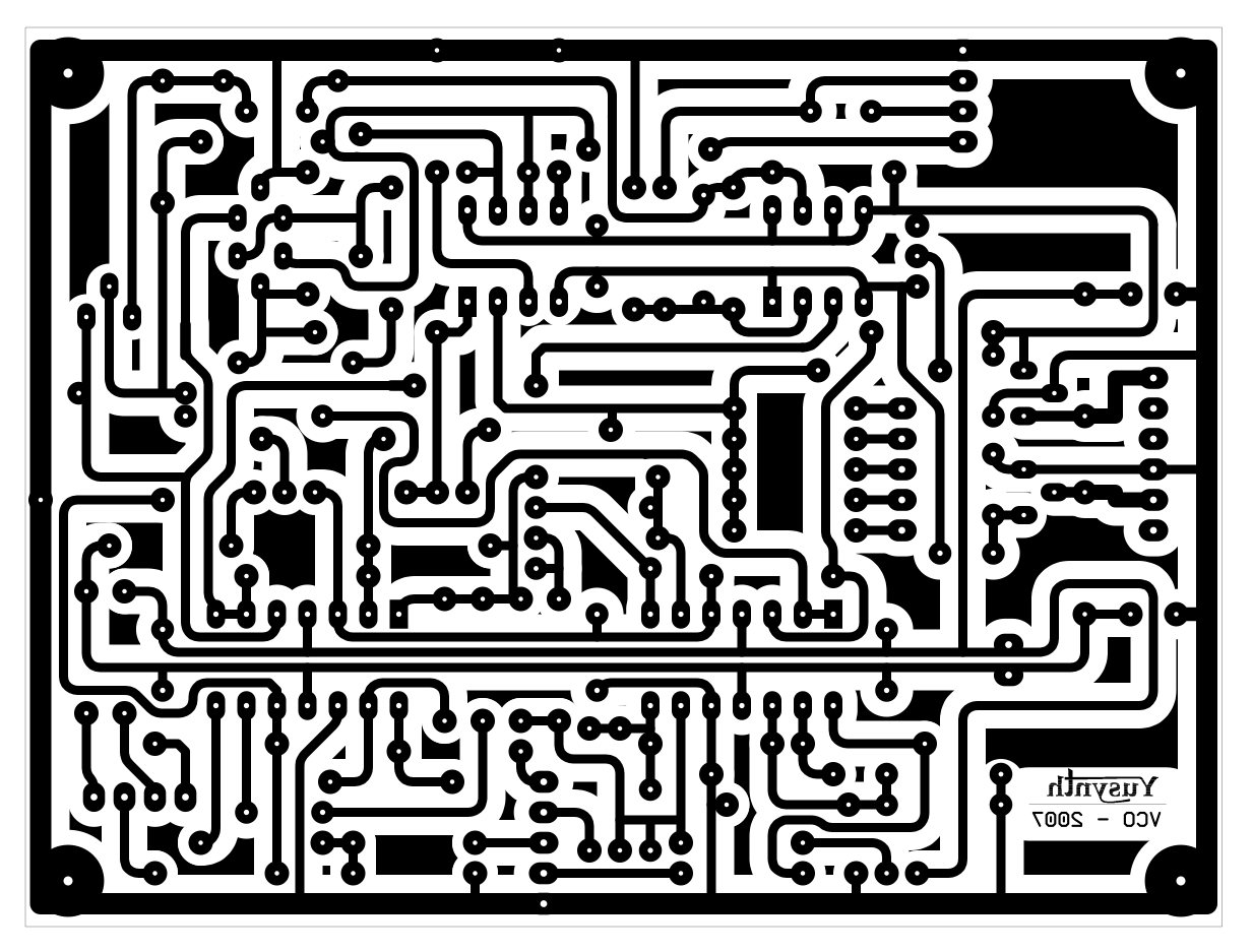
Schematics |
 |
|
DESIGN NOTE :
I have received a lot of emails concerning the voltage regulators used in the circuit. Here is an explaination for the reason why they are there. FAQs :
The aim of using these regulators is not to provide +15V and -15V as one would think first. As a matter of fact, because of the lack of voltage overhead and the low current draw they will rather deliver something like 14.2V and -14.2V. This is not a design error but was done on purpose : they are here to isolate the power supply circuit of the VCO core from the general power supply while providing a reference voltage of +/-14.2V. This helps very much in increasing the stability of the VCO. As such, all the circuit of the VCO core was designed considering the voltage drop through the regulators, and it is a very important point. As such, if one would like to remove/bypass these regulators, one would need to recalculate many resistor values of the VCO core to have it working as expected. In conclusion, they are there for a good reason ;-) |
|
|
|
|
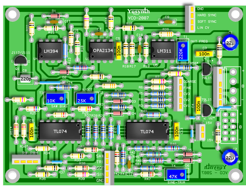
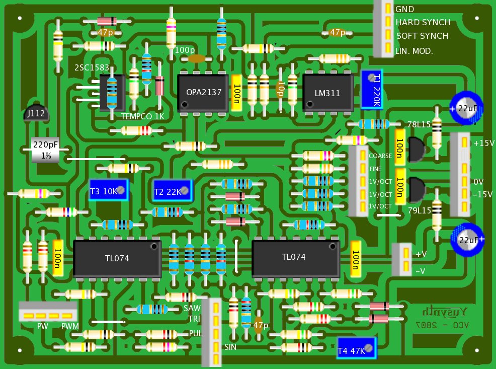
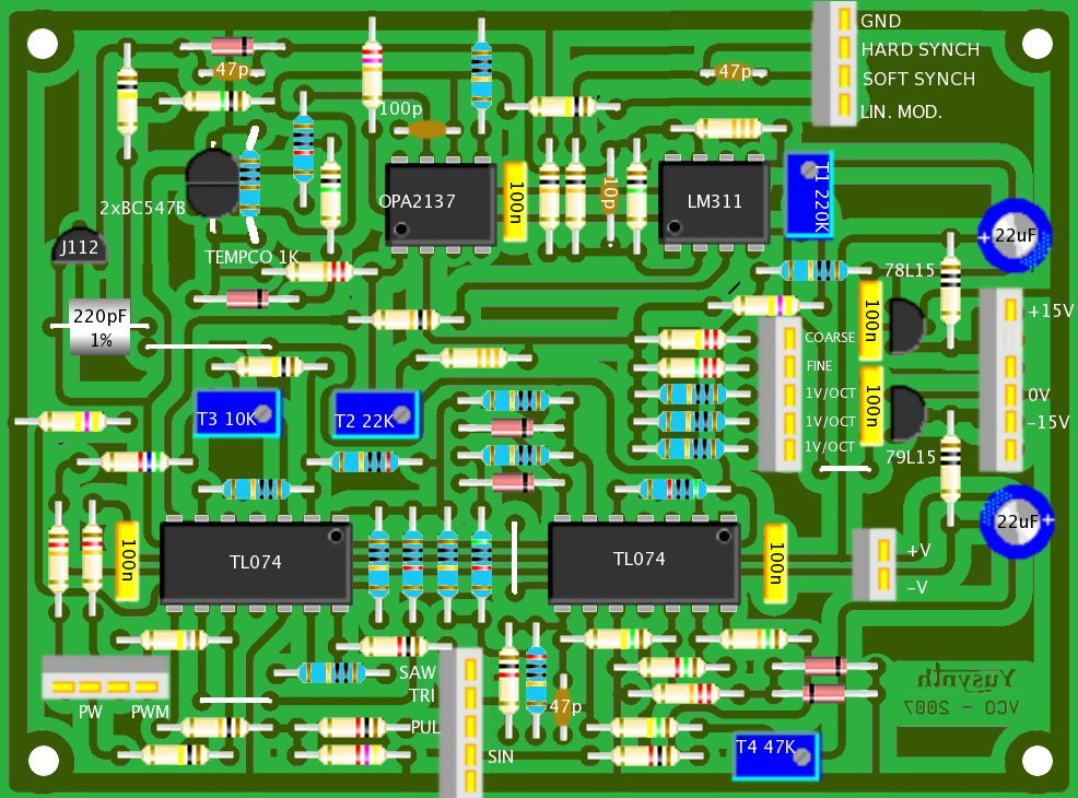
Components and building details |
|||||||||||||||||||||||||||||||||||||||||||||||||||||||||||||||||||||||||||||||||||||||||||||||||||||||||||||||||||||||||||||||||
|
|||||||||||||||||||||||||||||||||||||||||||||||||||||||||||||||||||||||||||||||||||||||||||||||||||||||||||||||||||||||||||||||||
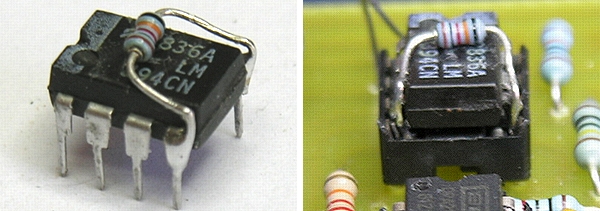
| IMPORTANT NOTE : for C8 use a
high grade low temperature drift capacitor
(styroflex or silver mica) If you choose to use a SSM2210 instead of a LM394, the value of R15 (10K) must be increased to 100K. NOTE CONCERNING THE AS394 : some people using AS394 as a replacement for the LM394 had difficulties with the pinout becaus of an ambiguous marking AS394 : Famous LM394 matched
transistors analogue made in Latvia. NB!
transistor configuration is the same, but pins are
shifted up but futhermore there are ambiguous red
spot on the IC. When using these on the
YuSynth VCO PCB which is designed for standard
LM394 pinout, you need to cut pins 1 and 8 off,
and shift the IC up in the socket- pinout below
explains it all - well we thought it did but Bob B
asked for clarification as to which is pin 1 as it
is confusing with those red blobs. We agree so
armed with a meter on the diode range revealed
that the small red dot is next to pin 5. The notch
in the case is at the top of the chip. 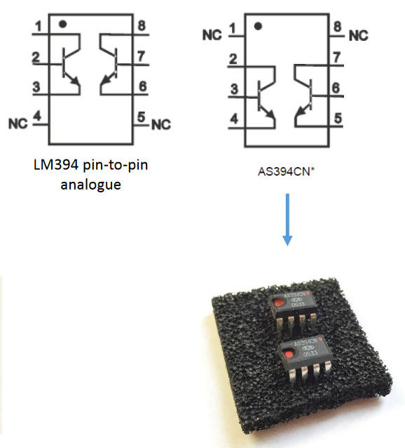 ` |
|||||||||||||||||||||||||||||||||||||||||||||||||||||||||||||||||||||||||||||||||||||||||||||||||||||||||||||||||||||||||||||||||
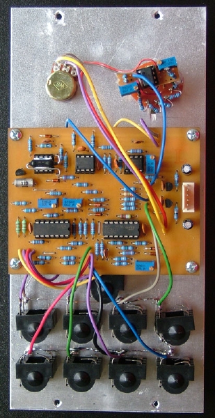
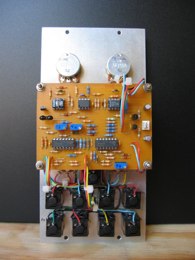
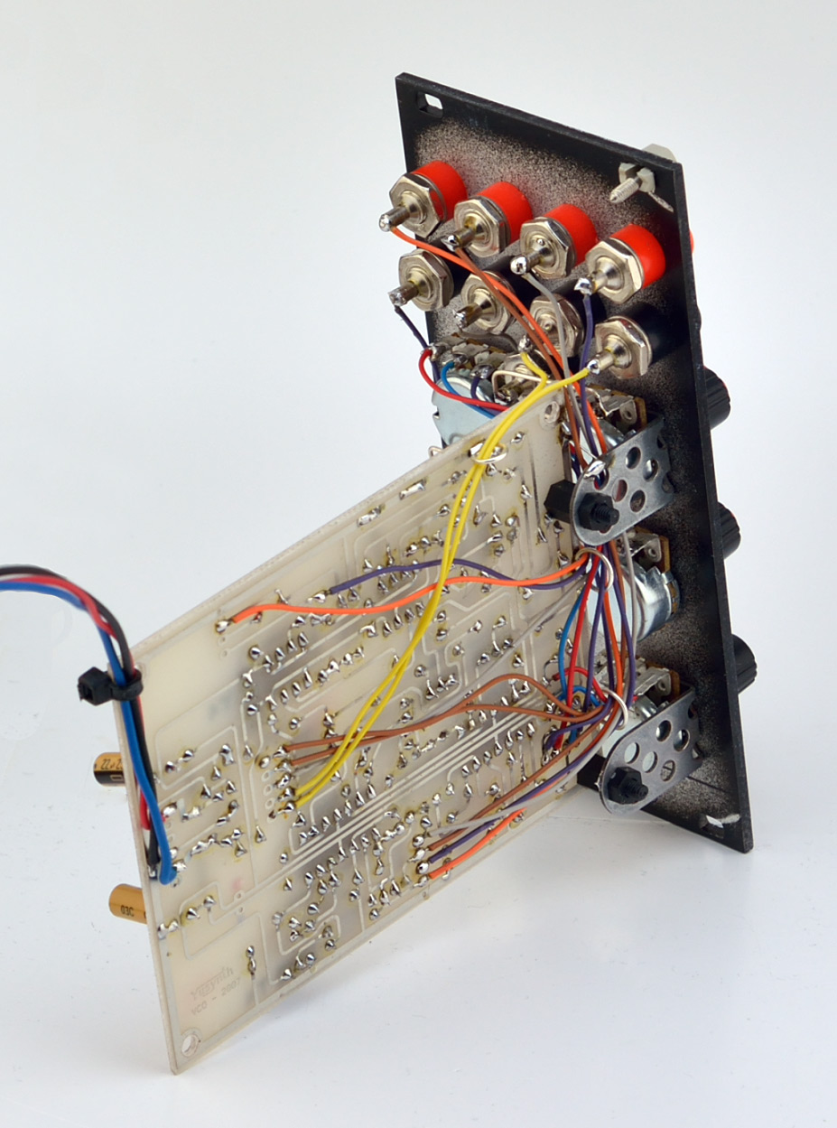
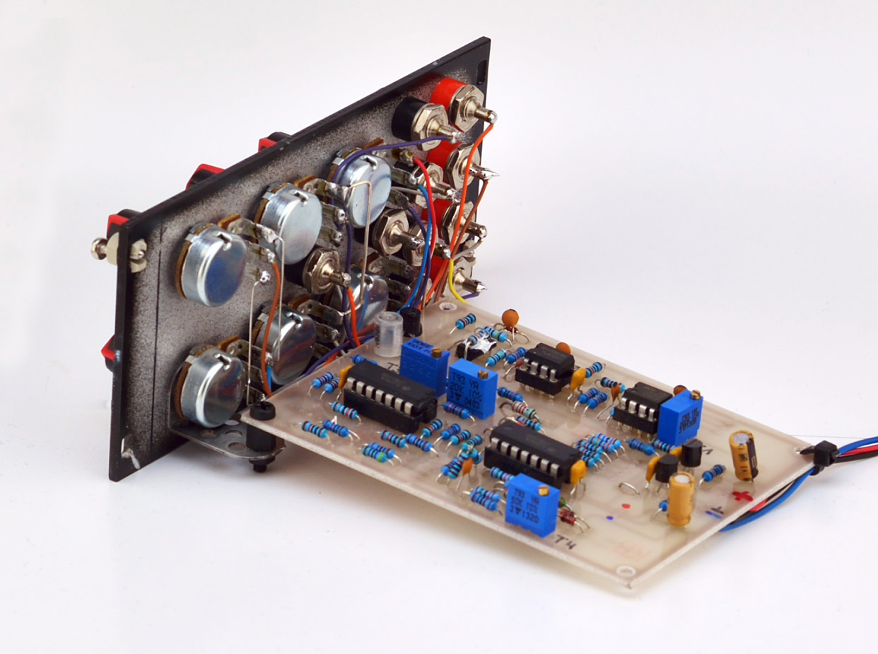
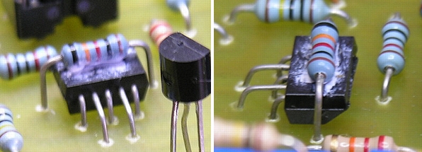
| Thermal coupling Thermal
coupling between the tempco resistor and the
transistor pair of the exponential converter
is an important condition for insuring a
good stability of the VCO. The following
pictures show how to install these critical
components on the PCB.
|
|||||||||||||||||||||||||||||||||||||||||||||||||||||||||||||||||||||||||||||||||||||||||||||||||||||||||||||||||||||||||||||||||
|
|||||||||||||||||||||||||||||||||||||||||||||||||||||||||||||||||||||||||||||||||||||||||||||||||||||||||||||||||||||||||||||||||
Proposed modification of the tempco section Mariano from Dallas,
Texas has moded the VCO in order to use an easy to
source NTC resistor as a replacement for the PTC
tempco resistor. This mod is described as well as
other mods in a PDF file located at the end of
this page in the Gallery section.
Thanks Mariano !
|
|||||||||||||||||||||||||||||||||||||||||||||||||||||||||||||||||||||||||||||||||||||||||||||||||||||||||||||||||||||||||||||||||
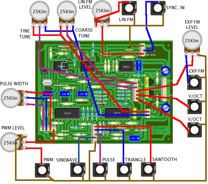
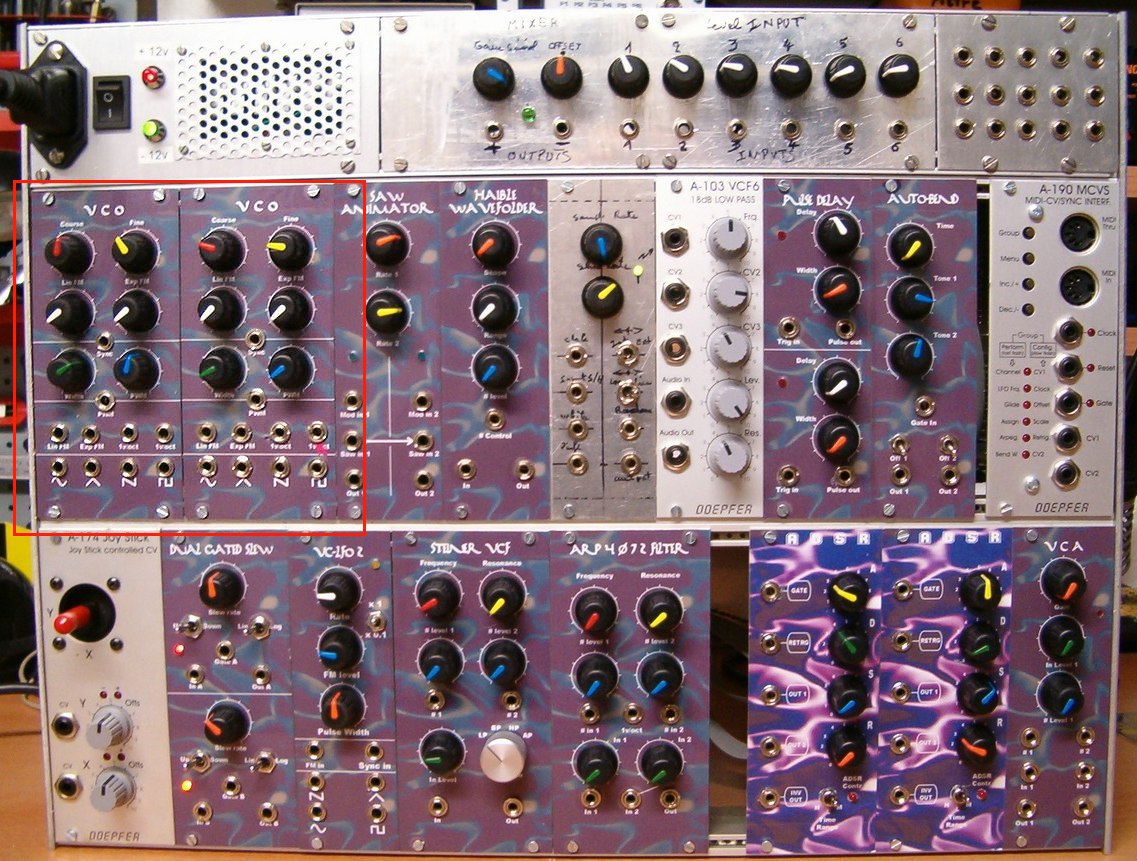
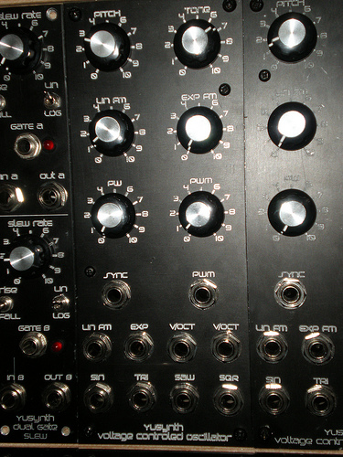
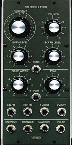
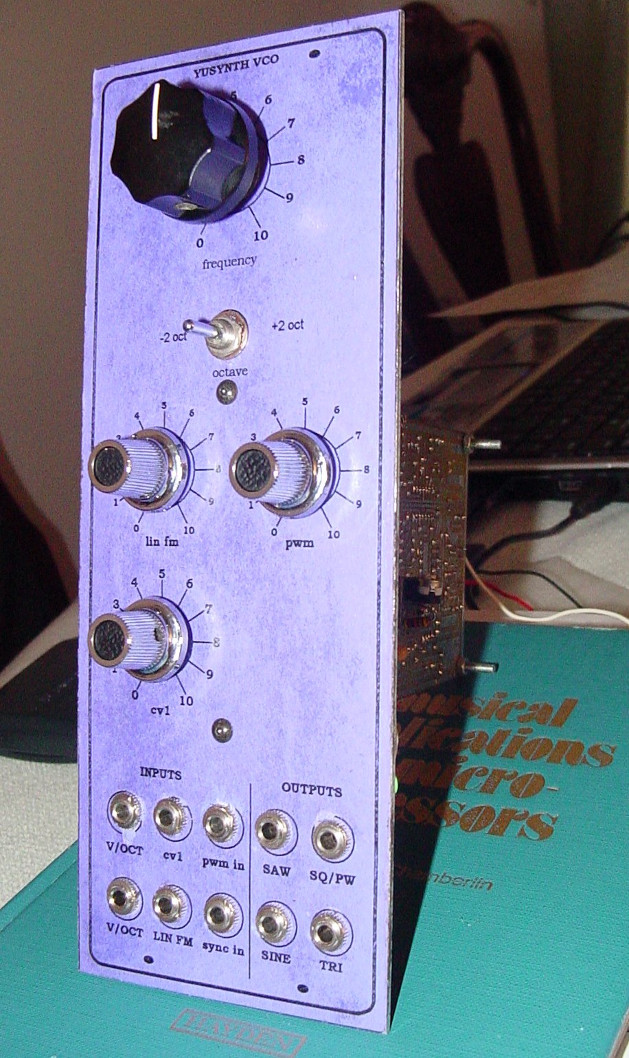
| Wiring Wiring option : the
SYNC IN jack may be either connected to the
HARD SYNCH or the SOFT SYNCH connector
depending on your taste. You may even add a
switch on the front panel in order to select
between the two hard synch modes.
|
|||||||||||||||||||||||||||||||||||||||||||||||||||||||||||||||||||||||||||||||||||||||||||||||||||||||||||||||||||||||||||||||||
 |
|
|
|
|
Setting and trimming
|
|
For setting and
trimming of the VCO, you need a good Oscilloscope, a
good source of control voltage (calibrated CV/GATE 5
octave keyboard) a good voltmeter (at least 4000
pts), a digital tuner (I am using a Korg CA tuner)
and/or a good frequency counter.
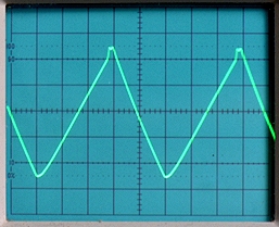
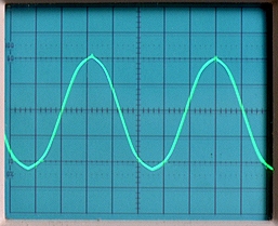
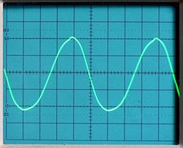
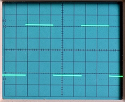
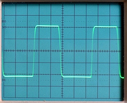
WAVESHAPE CONVERTER SETTING
V/OCT TRACKING
TUNING
|
||||||||
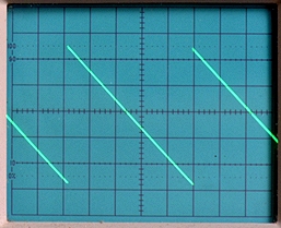
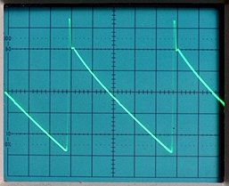
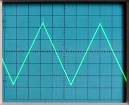
Waveshapes - vertical
scale : 2V/square,
0V on the middle horizontal line
|
|
|
References |
Understanding TEMPCO  Ian Fritz Sawtooth VCO |
|
 |
 |
||
| Name : Mariano Pseudo : Dhar2kma Modular project : Location : Dallas, Texas, USA Website : |
Name : Czaba
ZVEKAN Modular project : Location : Basel, Switzerland Website : |
Name : Patrick
Pseudo : Baronrouge Modular project: JHC live lab Location Toulon, France Web site : http://myspace.com/patjhc |
||
 |
  |
 |
||
| Name : Julien Modular project : Location : Website : |
Name : Pseudo : Sebo Modular project : Location : Argentina Website : http://www.cosaquitosenglobo.com.ar |
Name : Julien Modular project : Location : Website : |
||
  |
 |
 |
||
| Name : Zarko Modular project : Location : Gardanne, France Website : |
Name : Pseudo : Tudy Modular project : Yusynth 17U Location : Brno, Czech Republic Website :www.insania.freemusic.cz |
Name : Balazs Varga Pseudo : vinnui Modular project : Overmind modular Location : Hungary Website : http://vinnui.blogspot.com/ |
||
 |
   |
|||
| Name : Jim Coun Modular project : Location : Belgium Website : |
Name : Peter Hostermann Modular project : Location : Germany Website : http://www.peter-hostermann.de |
|
|||
|
|


