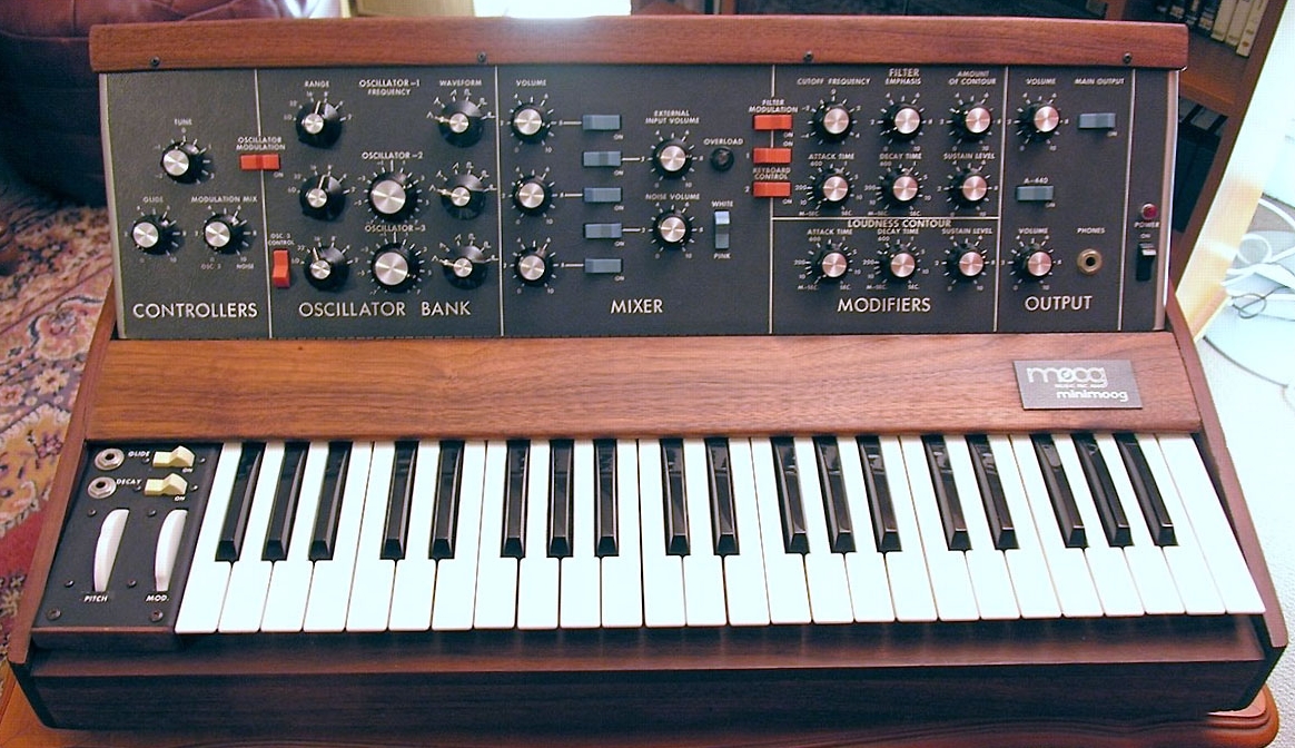
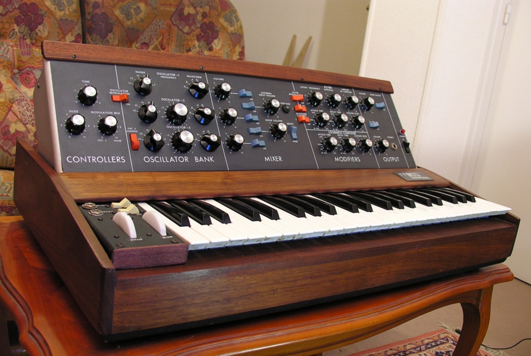
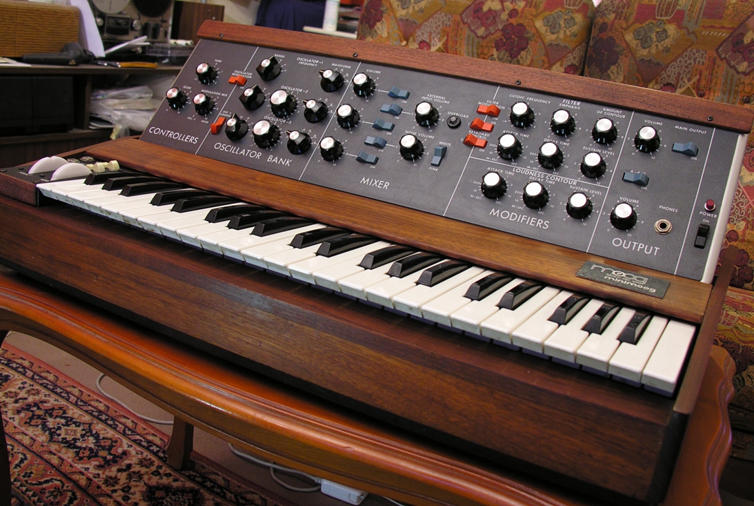
Moog Minimoog D monophonic synthesizer
This is the must have analogue synthesizers, a legend with genuine sonic qualities.  This is a model from 1973 with the old 
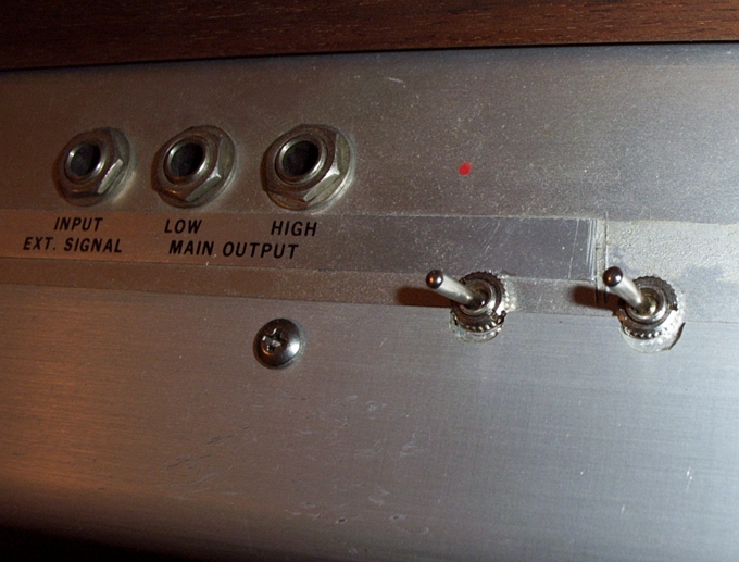
oscillator board.

Modifications : I added synchro slaving of oscillators 2 and 3 to oscillator 1. The switches are hidden behind the upper wood band.


Goodies

Here you'll find the Blue prints of the wood cabinet (Thanks to John Riesenman).

Minimoog schematics (thanks to Jack Palance)


Patch sheets

I have designed  a nice patch template for saving my own patches. You can download the blank patch sheet from this link . Now it's up to you create nice patches and save them with this template.
Here is an example of the patch of an infamous Minimoog lead...


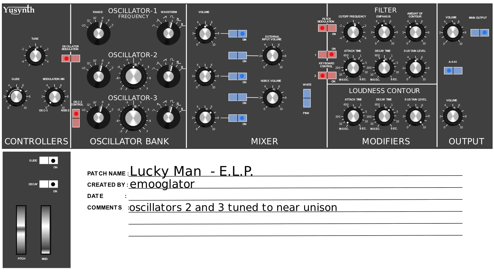
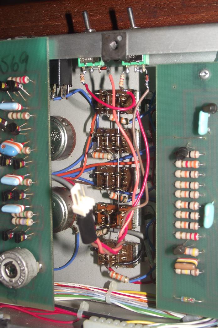
Synchro for OSC2 & OSC 3 (after Kevin Lightner)

The mod consist in adding two lever switch (hidden behind the top wood strip of the front panel) which makes possible to slave OSC2 & OSC3 to OSC1.
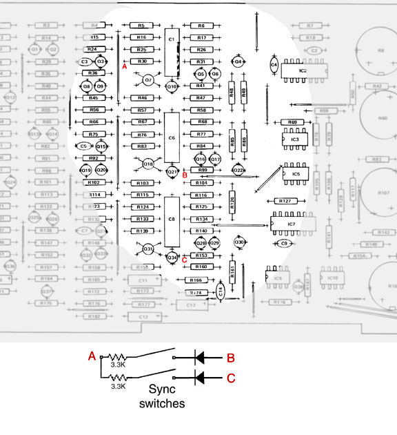
The modification is based on the instructions published by Kevin Lightner on his www.synthfool.com web site.
The modification requires two diodes (1N4148), two 3.3K resistors, two lever SPDT switches, a three pins male connectors with leads and a three pins female connector with leads.
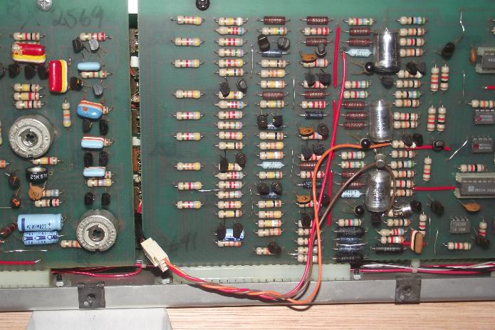
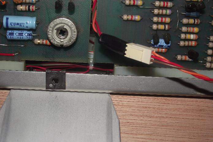


Here is the modification of my 1973 Minimoog


In order to facilitate the maintenance of the oscillator board, I use a three wire connector between the parts to be fixed on the chassis (resistors, diodes and switches) and the connections on the oscillator board.
Solder the red wire to point A as shown, solder the orange wire to point B and the brown wire to point C.

The modified oscillators board. Note the three wires connector.

Detail of the connection

Wiring of the resistors and diodes to the switches.

Switches installed on the chassis behind the top wood band.


Enhancing the pitch stability of old oscillator boards


Curiously enough, although the electronic circuits integrates tempco (temperature compensation)  resistors, the pitch stability of old oscillator boards is far from ideal. When analyzing the component layout it is clear that problem come from the fact the tempco resistors are located too far away from the two transistor arrays involved in the V/OCT conversion. To ensure a good temperature compensation the tempco resistors (R20 OSC1, R71 OSC2 and R119 OSC3) ought to be closely associated with the transistor arrays. The modification consists in desoldering the tempco resistors, solder leads to them and gluing them to the transistor arrays (IC2 OSC1 & OSC2; IC7 OSC3).

To correct this, we can move the tempco resistors (R19,R71,R119) as close as possible to the corresponding transistor arrays (IC2 et IC7) in order to obtain a quick and efficient feedback between these components.
  • Unsolder R20 from the printed circuit board, then solder a pair of wires to the legs of R20 on one side and to the corresponding holes on the PCB on the other side. Then R20 is inserted inside the IC socket of IC2 under IC2 (no need to glue R20, it will stay in place).
  • Unsolder R71 from the printed circuit board, then solder a pair of wires to the legs of R71 on one side and to the corresponding holes on the PCB on the other side. Then R71 is placed on top of IC2 and tied to it with thin wires (sewing wire or nylon wire).
  • Unsolder R119  from the printed circuit board, then solder a pair of wires to the legs of R119 on one side and to the corresponding holes on the PCB on the other side. Then R119  is inserted inside the IC socket of IC7 under IC7 (no need to glue R119, it will stay in place).
One may also use thermal grease to ease thermal exchanges between components but this is not compulsory to do so.

This modification is really worth being made because it dramatically reduces the warming delay before playing in tune : less than 5 minutes is required after the modification while 20 minutes at least were required before. Furthermore, the tuning between oscillators becomes nearly immediate.

BEFORE MODIFICATION
Location of the tempco resistors (big black resistors)

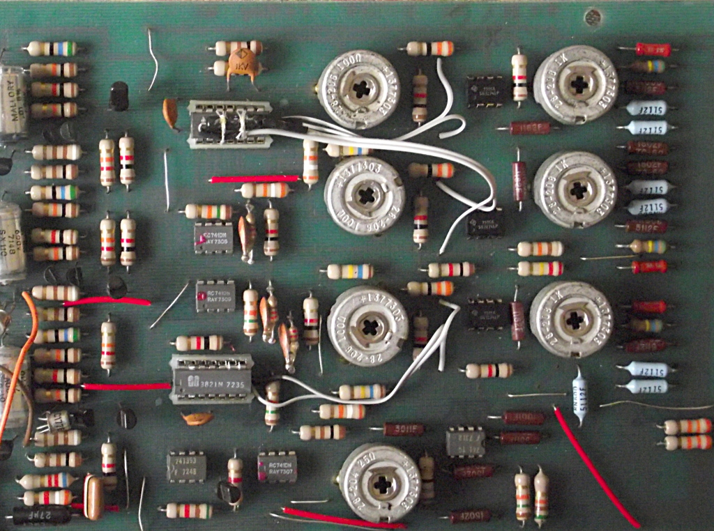
Connexion des résistances tempco sur et sous les réseaux de transistor

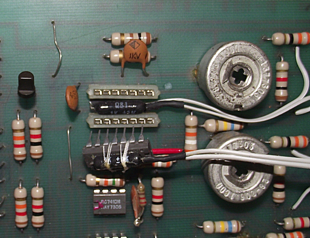
Detail of the fixation of R19 & R70 beneath and onto IC2