| Update : sep 16th, 2019 |
Wavefolder
|
En français
 |
 |
back to summary |
 |
 |
| Description |
| Update : sep 16th, 2019 |
Wavefolder
|
En français
|
|
back to summary |
|
|
| Description |
|
|
|
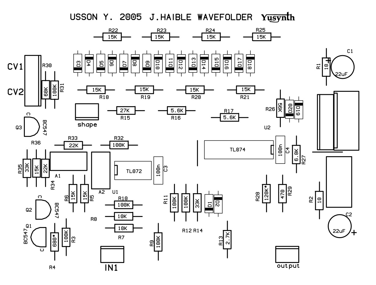
Schematics |
 |
|
This circuit is made of three parts :
the first one is based on U2, Q1 and Q3 and is a voltage
controlled amplifier (VCA) and accepts an input signal
ranging from -10V et +10V with a control voltage (CV1)
ranging from 0 to 15V. The second part made of
U1b, U1c and U1d and diodes D1 à D20 is actually Jürgen
Haible's walvefolder B
By the way, if you need to modify the voltage range of the input and output signals, it is just a matter of changing the values of R20 & R21 for the input signal and that of R17 & R18 to adjust the output level. |
|
|
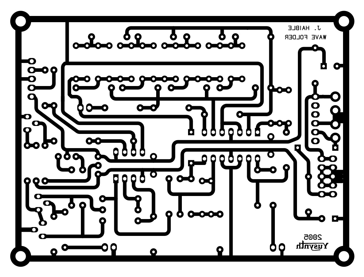
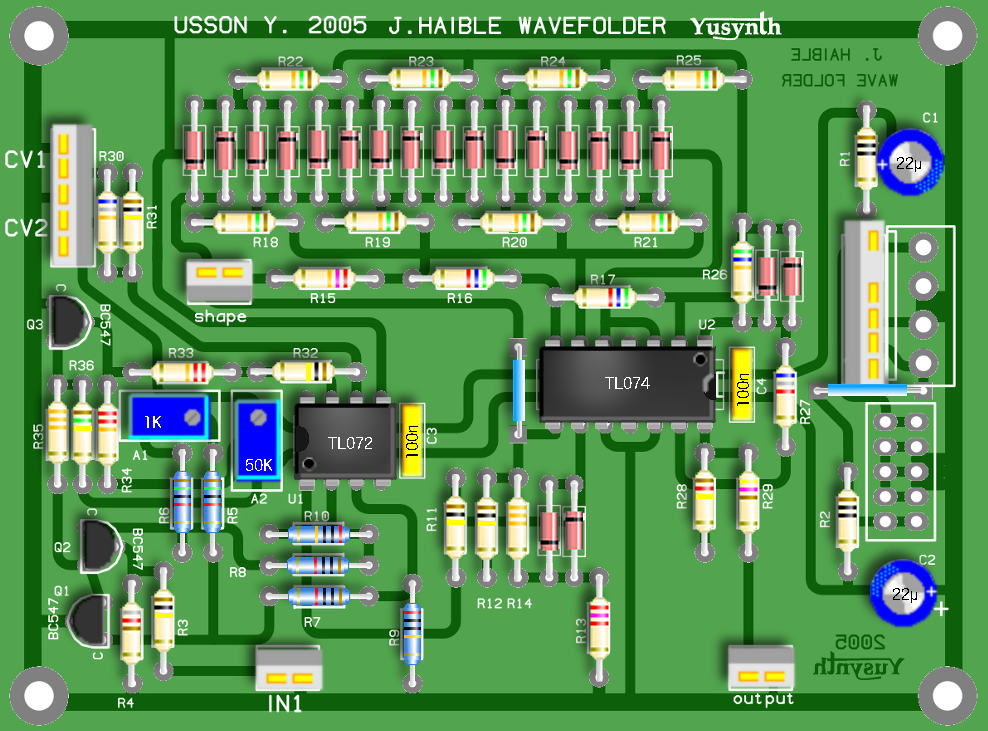
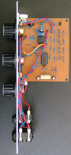
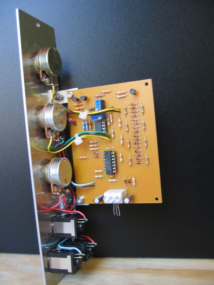
Printed circuit boards and component layout |
|||
|
|
|
Components and building details |
||||||||||||||||||||||||||||||||||||||||||||||||||||||||||||||||||||||||||||||
|
||||||||||||||||||||||||||||||||||||||||||||||||||||||||||||||||||||||||||||||
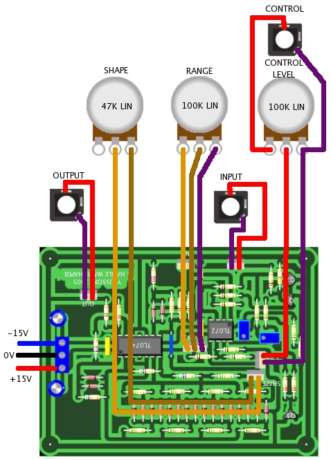
| Wiring |
||||||||||||||||||||||||||||||||||||||||||||||||||||||||||||||||||||||||||||||
 |
|
|
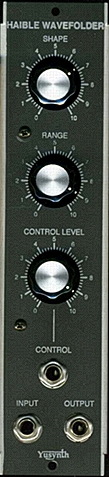
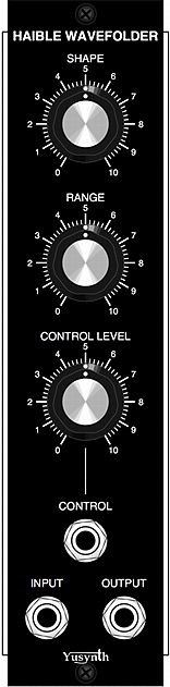
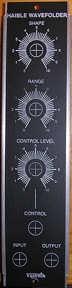
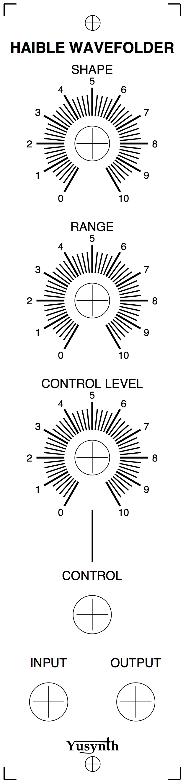
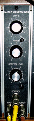
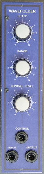
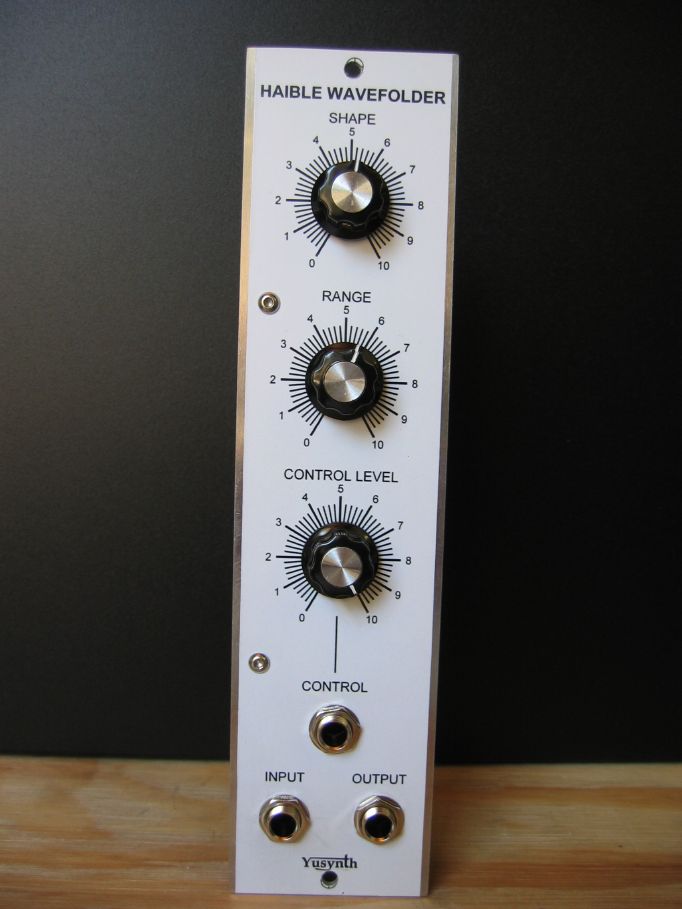
| Front panel |
|||
|
|
|
Setting and trimming
|
|
Trimming is quite
easy if you use matched NPNs for Q1 and Q2, and 1%
tolerance resistors for R22 to R27. You will need a
dual trace scope, a DVM and a sinewave generator.
Using 10 turn trimmers is a little bit more
expensive than using 1 turn but makes it easier to
adjust with high accuracy.
|
|
|
References |
||||||||
There are many
different variant of wavefolder, here are some
valuable links:
|
 |
 |
 |
| Name : Czaba
ZVEKAN Modular project : Location : Basel, Switzerland Website : |
Name :
Oliver ABPLANALP Modular project : Cave studio Location : Schaffhausen, Switzerland Website : http://www.cavestudio.ch |
Name :
Patrick
Pseudo : Baronrouge Modular project: JHC live lab Location Toulon, France Web site : http://myspace.com/patjhc |
  |
  |
|
| Name
: Pseudo : Sebo Modular project: Location: France Web site :http://www.cosaquitosenglobo.com.ar |
Name
: Frédéric Monti Pseudo : Zarko Modular project: Location: Gradanne, France Web site : |
|
|||
|
|