Modified : feb. 12th. 2009

CV standards

En français
back to summary


Description

This utility modules provides switchable discrete CVs with useful intervals such as :
  • octaves; eleven 1V steps from 0V to 10V  (useful to control the yusynth VCOs which have no octave range switches);
  • semitones; eleven 1/12 V steps from -0.4166V to 0.4166V (useful to detune a VCO with semitone intervals)
OCTAVE
VALUE
SEMITONE
VALUE
0
0 V
-5
-0.4166 V
1
1 V
-4
-0.3333 V
2
2 V
-3
-0.2500 V
3
3 V
-2
-0.1666 V
4
4 V
-1
-0.0833 V
5
5 V
0
0 V
6
6 V
+1
0.0833 V
7
7 V
+2
0.1666 V
8
8 V
+3
0.2500 V
9
9 V
+4
0.3333 V
10
10 V
+5
0.4166 V

These stepped CVs are available independently on three voices and for each voice three buffered outputs are provided in order to drive more than one module (these are not multiples but true electrically separated and buffered outputs).

Also for each voice, an external CV can be summed to the stepped voltages. These inputs are intended for connecting external controllers such as a keyboard or a sequencer. Note that the input of voices 2 and 3 are defaulted to the previous input. For example if one connects a keyboard CV to IN #1 then this CV is echoed on the two others voices. But if one connects three different CVs on the three inputs, then each voice is only driven by the corrsponding input.

Schematic


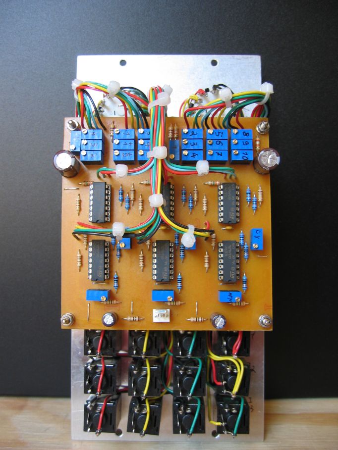
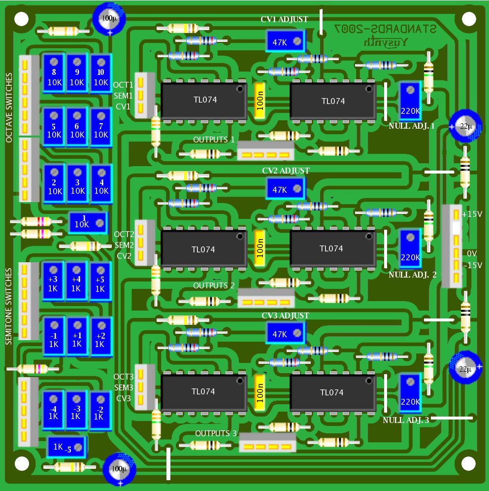
Printed Circuit Board and Component Layout

NOTE : the PCB and a component kit for this module are now made available by Bridechamber
PCB design


Layout


Download the schematic as a PDF file 
Download the PCB as a PDF file 

WARNING ! The document is formatted to be printed directly on a mylar for photo-etching or a "press & peel" paper. Make sure that when the printed face of mylar is in contact with the copper side of the PCB, the lettering can be read normally.
IMPORTANT NOTE : R7 must be 156K. Because this is no standard value for a resistor, we will have to use some trick. As a matter of fact, this can be obtain by connecting a 180K resistor and a 1.2M  resistor in parallel. To do so, install the 150K resistor as shown on the component overlay and solder the 1.2M on the track side to the same pads as for the 180K resistor.
,

List of parts and building instructions
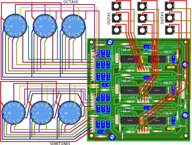
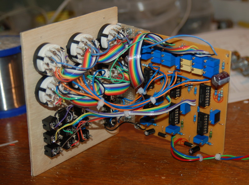
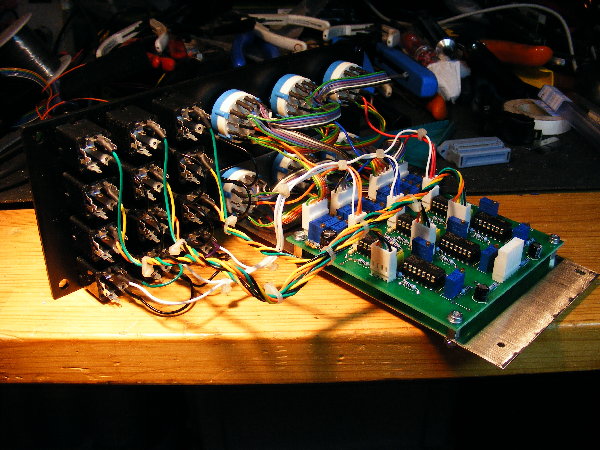
reference
value
number
U1,U2,U3,U4,U5,U6
TL074
6
R1,R2
10 ohm
2
R17,R18,R19,R27,R28,R29,R37,R38,R39
100 ohm
9
R6,R8
470 ohm
2
R4
4.7k
1
R3 39k
1
R14,R16,R24,R26,R34,R36 100K 0.1% (take a batch of 1% and select those within 0.1%)
6
R7
156K (a 180K in parallel with a 1.2M)
1
R5,R12,R22,R32
180K
4
R10,R11,R13,R20,R21,R23,R30,R31,R33 200K 0.1% (take a batch of 1% and select those within 0.1%) 9
R15,R25,R35
1M
3
R9,R19,R29
3.3M
3
C5,C6,C7 100nF 3
C1,C2 10µF or 22µF/35V electro. 2
C3,C4
100µF/35V electro.
2
T11,T12,T13,T14,T14,T15,T16,T17,18,T19,T20
1K 10 (or 15 or 25) turn trimmer 10
T1,T2,T3,T4,T5,T6,T7,T8,T9,T10
10K 10 (or 15 or 25) turn trimmer 10
T21,T23,T25
47K 10 (or 15 or 25) turn trimmer 3
T22,T24,T26
220K 10 (or 15 or 25) turn trimmer 3
Jk1,Jk2,Jk3,Jk4,Jk5,Jk6,Jk7,Jk8,Jk9,Jk10,Jk11,Jk12
6,5 mm jack socket
12

Wiring
Because the wiring is very dense, I split the wiring diagram into two schematics
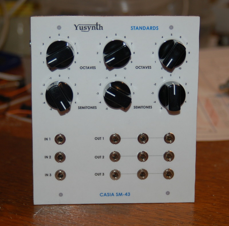
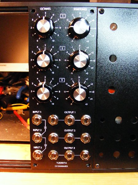
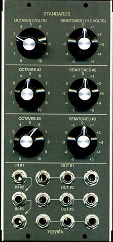
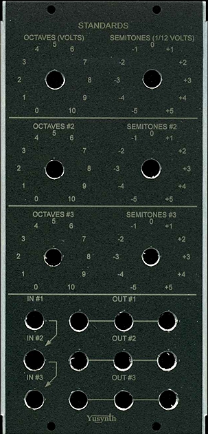
             

Front plate
Panel design


Download the silkscreen mask as a PDF file 


Download the silkscreen mask as a  JPEG file 


Trimming


It is important to use a high precision DVM at least 4000 pts.
  • Set all the OCTAVE rotaries to the 0 position (counter clockwise position) and the SEMITONES rotaries to the 0 position (middle position)
Offset trimming :
  • Connect the DVM to one of the outputs of channel/voice #1 (use 10mV/20mV DC range)
  • Adjust T22 such that you measure 0mV +/- 0.2mV at the output.
  • Connect the DVM to one of the outputs of channel/voice #2 (use 10mV/20mV DC range)
  • Adjust T24 such that you measure 0mV +/- 0.2mV at the output.
  • Connect the DVM to one of the outputs of channel/voice #3 (use 10mV/20mV DC range)
  • Adjust T26 such that you measure 0mV +/- 0.2mV at the output.
Octave trimming :
  • Connect the DVM to one of the outputs of channel/voice #1 (use 1V/2V DC range)
  • Set the octave rotary (channel #1) to 1
  • Adjust T10 (noted 1 on the component layout diagram) such that you obtain 1V +/-0.001V at the output
  • Set the octave rotary (channel #1) to 2
  • Adjust T9 (noted 2 on the component layout diagram) such that you obtain 2V +/-0.001V at the output
  • Set the range of the DVM to 10V/20V DC
  • Set the octave rotary (channel #1) to 3
  • Adjust T8 (noted 3 on the component layout diagram) such that you obtain 3V +/-0.001V at the output
  • Set the octave rotary (channel #1) to 4
  • Adjust T7 (noted 4 on the component layout diagram)such that you obtain 4V +/-0.001V at the output
  • Set the octave rotary (channel #1) to 5
  • Adjust T6 (noted 5 on the component layout diagram)such that you obtain 5V +/-0.001V at the output
  • Set the octave rotary (channel #1) to 6
  • Adjust T5 (noted 6 on the component layout diagram)such that you obtain 6V +/-0.001V at the output
  • Set the octave rotary (channel #1) to 7
  • Adjust T4 (noted 7 on the component layout diagram)such that you obtain 7V +/-0.001V at the output
  • Set the octave rotary (channel #1) to 8
  • Adjust T3 (noted 8 on the component layout diagram)such that you obtain 8V +/-0.001V at the output
  • Set the octave rotary (channel #1) to 9
  • Adjust T2 (noted 9 on the component layout diagram)such that you obtain 9V +/-0.001V at the output
  • Set the octave rotary (channel #1) to 10
  • Adjust T1 (noted 10 on the component layout diagram) such that you obtain 10V +/-0.001V at the output

Semitone trimming :
  • Connect the DVM to one of the outputs of channel/voice #1 (use 1V/2V DC range)
  • Set the octave rotary (channel #1) to 0
  • Set the semitone rotary (channel #1) to -5
  • Adjust T20 (noted -5 on the component layout diagram) such that you obtain -0.4166V +/-0.0001V at the output
  • Set the semitone rotary (channel #1) to -4
  • Adjust T19 (noted -4 on the component layout diagram) such that you obtain -0.3333V +/-0.0001V at the output
  • Set the semitone rotary (channel #1) to -3
  • Adjust T18 (noted -3 on the component layout diagram) such that you obtain -0.2500V +/-0.0001V at the output
  • Set the semitone rotary (channel #1) to -2
  • Adjust T17 (noted -2 on the component layout diagram) such that you obtain -0.1666V +/-0.0001V at the output
  • Set the semitone rotary (channel #1) to -1
  • Adjust T16 (noted -1 on the component layout diagram) such that you obtain -0.0833V +/-0.0001V at the output
  • Set the semitone rotary (channel #1) to +1
  • Adjust T15 (noted +1 on the component layout diagram) such that you obtain 0.0833V +/-0.0001V at the output
  • Set the semitone rotary (channel #1) to +2
  • Adjust T14 (noted +2 on the component layout diagram) such that you obtain 0.1666V +/-0.0001V at the output
  • Set the semitone rotary (channel #1) to +3
  • Adjust T13 (noted +3 on the component layout diagram) such that you obtain 0.2500V +/-0.0001V at the output
  • Set the semitone rotary (channel #1) to +4
  • Adjust T12 (noted +4 on the component layout diagram) such that you obtain 0.3333V +/-0.0001V at the output
  • Set the semitone rotary (channel #1) to +5
  • Adjust T11 (noted +5 on the component layout diagram) such that you obtain 0.4166V +/-0.0001V at the output

External CV trimming :
  • Set all the OCTAVE rotaries to the 0 position (counter clockwise position) and the SEMITONES rotaries to the 0 position (middle position)
  • Connect the DVM to one of the outputs of channel/voice #1 (use 10V DC range)
  • Connect a calibrated voltage source set to 5.000V +/-0.001V to the IN #1 input
  • Adjust T21 such that you obtain 5.000V +/-0.001V at the output
  • Connect the DVM to one of the outputs of channel/voice #2 (use 10V DC range)
  • Connect a calibrated voltage source set to 5.000V +/-0.001V to the IN #2 input
  • Adjust T23 such that you obtain 5.000V +/-0.001V at the output
  • Connect the DVM to one of the outputs of channel/voice #3 (use 10V DC range)
  • Connect a calibrated voltage source set to 5.000V +/-0.001V to the IN #3 input
  • Adjust T25 such that you obtain 5.000V +/-0.001V at the output


Name :
Pseudo : Etaoin
Modular project : Casia MS01
Location : Utrecht, Netherlands
Website : www.casia.org/modular


Name :
Pseudo :
Modular project :
Location :
Website
Name : Frederic Monti
Pseudo : Zarko
Modular project :
Location : Gardanne, France
Website
back to summary