| Update july 8th, 2017 |
Dual balanced modulator
(ring modulator) |
En français
 |
 |
back to summary |
 |
 |
| Description |
| Update july 8th, 2017 |
Dual balanced modulator
(ring modulator) |
En français
|
|
back to summary |
|
|
| Description |
|
|
|
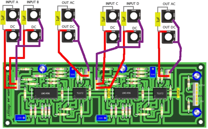
Schematic diagram
|
 |
|
The schematic of this balanced
modulator is directly inspired by that of the Elektor's
Formant
 (which is a mere
adaptation of the application schematic of the LM1496
datasheet, see at the end of this page). I have only
changed the values of the input resistors in order to
make the input signal levels compatible with the
Moog/Dotcom standards (10V peak to peak) I also added an
output stage that amplifies the output signal by 6.8 in
order to obtain 10Vpp. (which is a mere
adaptation of the application schematic of the LM1496
datasheet, see at the end of this page). I have only
changed the values of the input resistors in order to
make the input signal levels compatible with the
Moog/Dotcom standards (10V peak to peak) I also added an
output stage that amplifies the output signal by 6.8 in
order to obtain 10Vpp. |
|
|
|
|
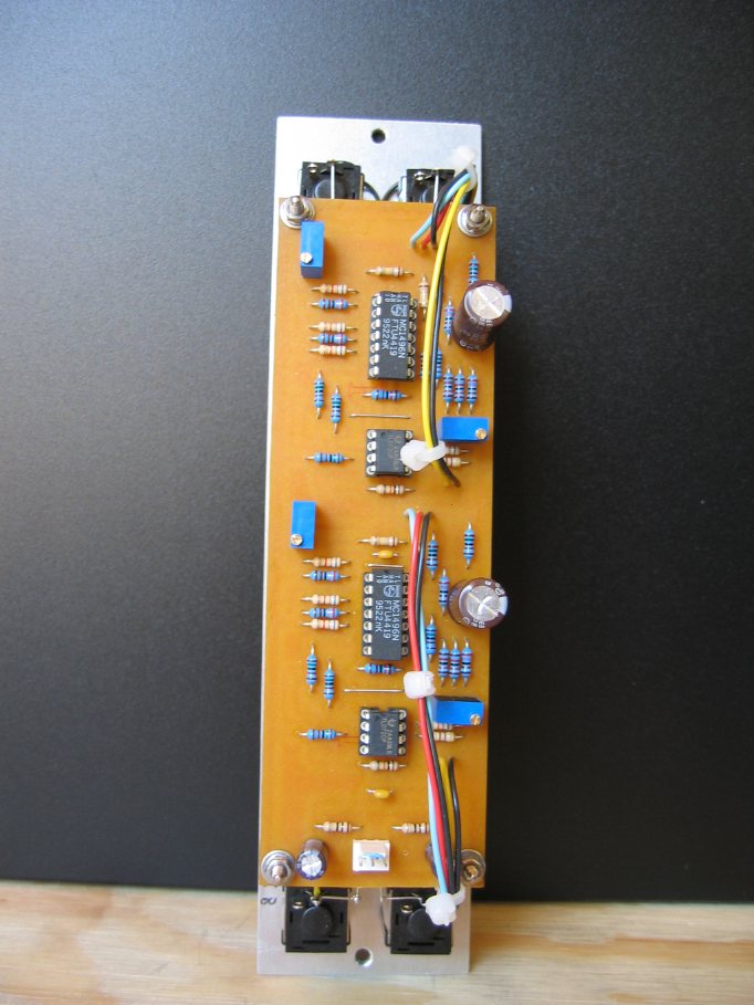
Building instructions
|
|||||||||||||||||||||||||||||||||||||||||||||||||||||||||||||||
|
|||||||||||||||||||||||||||||||||||||||||||||||||||||||||||||||
| Do not forget to solder the four straps. Use 1% resistors when indicated. | |||||||||||||||||||||||||||||||||||||||||||||||||||||||||||||||
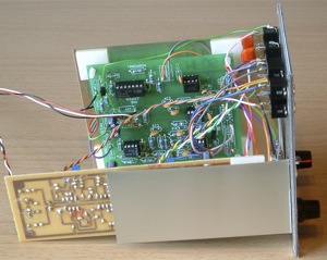
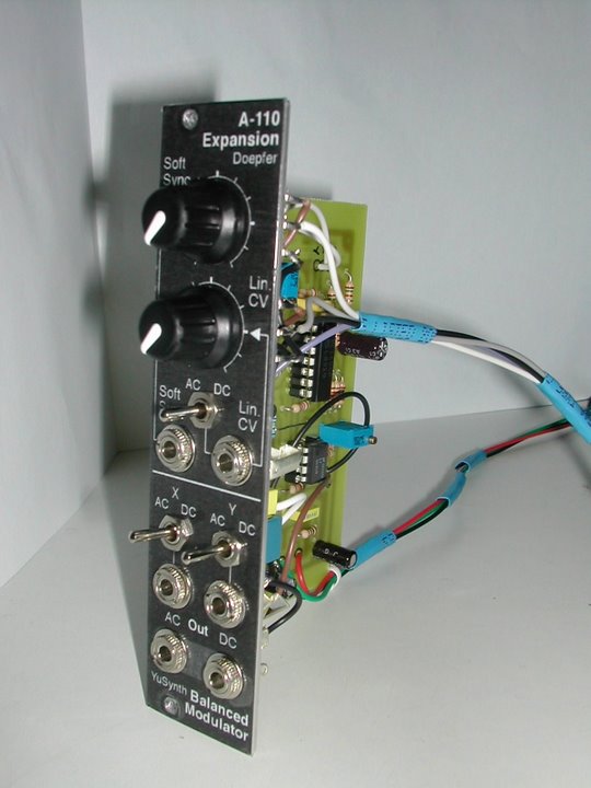
| Wiring |
|||||||||||||||||||||||||||||||||||||||||||||||||||||||||||||||
 |
|
|
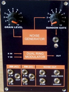
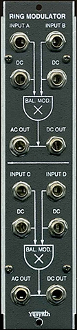
| Front panel |
|||
|
|
|
Settings and trimming
|
There are four trimmers
to adjust : A1 to A4. These trimmers are used for
cancelling the input signals. The settings are quite
simple, you will need a signal generator that delivers
a sinewave signal with a 10V (peak to peak) output
amplitude. Here is how to proceed :
|
|
|
References |
||||||||
|
  |
 |
  |
| Name : Pseudo : AndyR1960 Modular project : BroadWave Location : Manchester, UK Website : http://www.solarmaxx.co.uk/ |
Name :
Jordi Pseudo : vcfool Modular project : Location : Manchester, UK Website : |
Name : Federic Monti
Pseudo : Zarko Modular project: Location Gardanne, France Web site : |
|
|||
|
|