| Modified : feb. 19th 2017 |
Quadrature VC-LFO
|
En français
 |
 |
back to summary |
 |
 |
| Description |
| Modified : feb. 19th 2017 |
Quadrature VC-LFO
|
En français
|
|
back to summary |
|
|
| Description |
|
|
|
Schematic |
 |
|
|
|
|
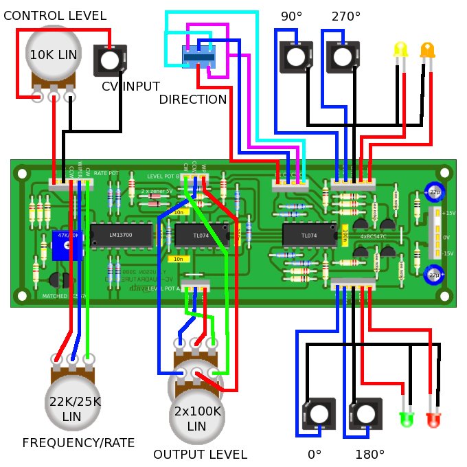
Printed Circuit Board and Component Layout
|
|||
|
|
|
List of parts and building instructions
|
||||||||||||||||||||||||||||||||||||||||||||||||||||||||||||||||||||||||||||||||||||||||||||||||||||||
|
||||||||||||||||||||||||||||||||||||||||||||||||||||||||||||||||||||||||||||||||||||||||||||||||||||||
| all resistors are 5% 1/4W unless
specified otherwise |
||||||||||||||||||||||||||||||||||||||||||||||||||||||||||||||||||||||||||||||||||||||||||||||||||||||
| Wiring |
||||||||||||||||||||||||||||||||||||||||||||||||||||||||||||||||||||||||||||||||||||||||||||||||||||||
 |
|
|
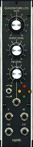
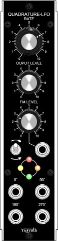
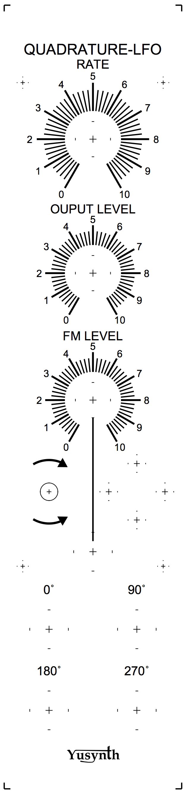
| Front plate |
||
|
|
|
Trimming
|
| Connect
an oscilloscope on the 0° output, (settings
1ms/square, 1V/square) Set the RATE potentiometer to 10, the FM LEVEL pot to 0 and the OUTPUT LEVEL to 10. The module must work as soon as powered however at startup the amplitude of oscillation is quite low (0.1V) and it takes some oscillation cycles to reach the normal amplitude of oscillation (something like -8V/+8V), it reaches its maximum amplitude. When, it's oscillating at its steady amplitude, set the frequency pot to the minimal rate (fully counter clockwise) then adjust the trimmer T1 in order to set the lower rate (the lowest rate achievable is around 30s per cycle). Now set the rate to approximately 1s per cycle, the LEDs should lit in turn, for example RED, then YELLOW, then GREEN, then ORANGE or conversely. If this is not the case swap the connections of the LEDs. Toggle the switch, now the LEDs must lit in the opposite direction. |
|
|
References |
Ian Fritz's
ChaQuO page :  More on Separd tones : More on Tritone paradox : |
| |
||
| Name : Pseudo : Modular project: Location : Web site : |
|
|
|||
|
|