| Update : dec. 31st, 2010 |
Envelope generator
ADSR |
En français
 |
 |
back to summary |
 |
 |
| Description |
| Update : dec. 31st, 2010 |
Envelope generator
ADSR |
En français
|
|
back to summary |
|
|
| Description |
|
|
|
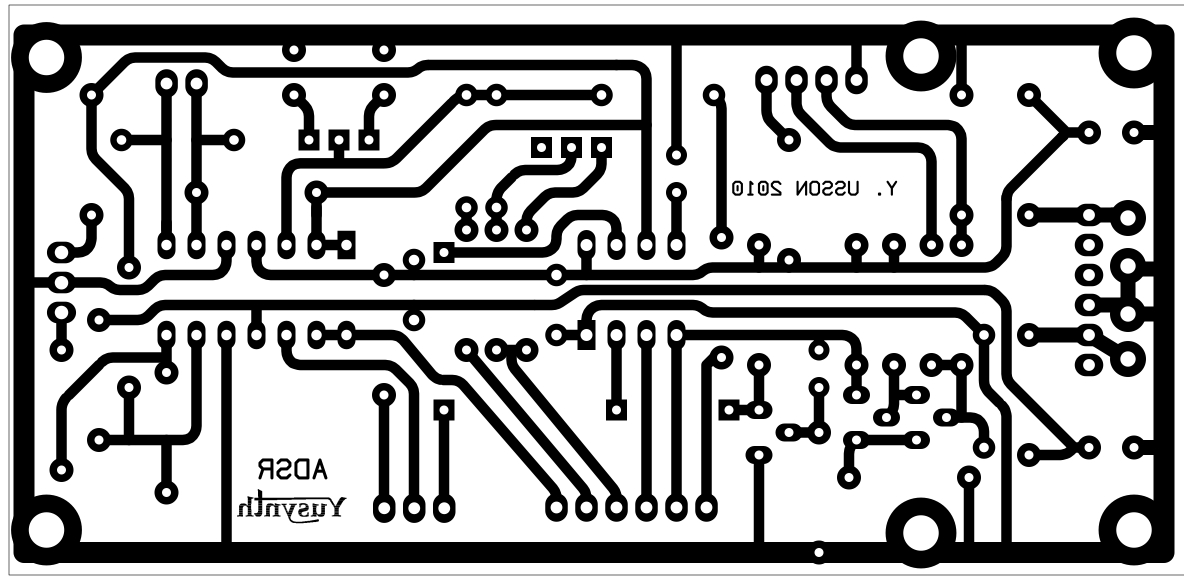
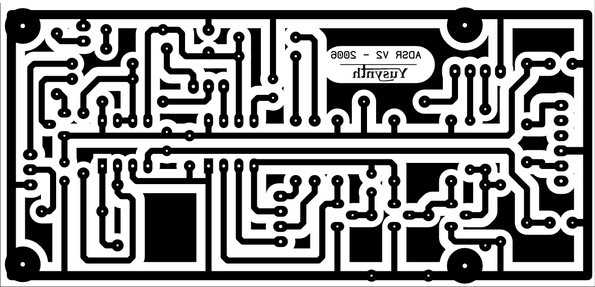
Schematic |
 |
|
The schematic of this module is
rather simple and uses very common components. The 555
core of the schematic is based on an original idea by Jonathan Jacky
 that was published in Electronics ("Two-chip generator
shapes synthesizer's sounds" Electronics #11, September 1980 : 137-138). This core has
inspired other DIYers (Tom G.-EFM, René Schmitz ). that was published in Electronics ("Two-chip generator
shapes synthesizer's sounds" Electronics #11, September 1980 : 137-138). This core has
inspired other DIYers (Tom G.-EFM, René Schmitz ). Q1 and Q2 operate as a Schmitt trigger and turn any input signal as a suitable GATE signal. D1 protects the circuit from negative voltages. The trigger threshold is 2V. Diodes D2 to D4 are used to dispatch the charge and discharge current of the timing capacity C7/C8 (10µF/35V tantalum) through the potentiometers P1,P2 & P4. The 7555 chip (U1) is wired as a monostable timer. One OPA (TL074) is used to buffer the SUSTAIN voltage and avoids interference with the DECAY settings (otherwise the DECAY time would be affected by the SUSTAIN level). Two OPAs are used as a simple voltage follower and a voltage inverter, respectively. The fourth OPA drives the control LED. |
|
|
|
|
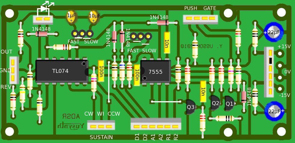
Components and building guide
|
||||||||||||||||||||||||||||||||||||||||||||||||||||||||||||||||||||||||||||||||||||
|
||||||||||||||||||||||||||||||||||||||||||||||||||||||||||||||||||||||||||||||||||||
| R17 : sets the range of
the inverted output, if you use a 150K for R17 the
inverted output will start from 10V (quiet state) to
0V (full range). If you don't install R17 (leave its
place empty) then the range will be 0V (quiet state)
to -10V (full range). |
||||||||||||||||||||||||||||||||||||||||||||||||||||||||||||||||||||||||||||||||||||
| Wiring |
||||||||||||||||||||||||||||||||||||||||||||||||||||||||||||||||||||||||||||||||||||
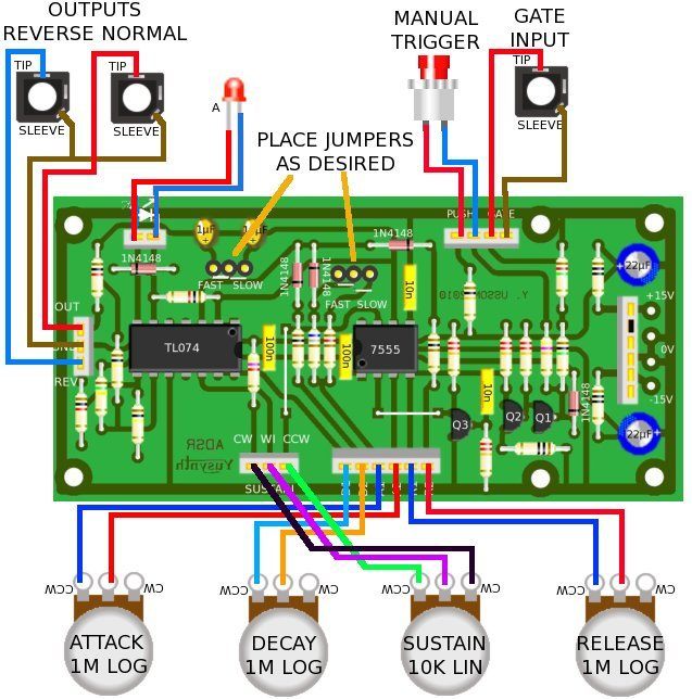 SHORT/LONG toggle switch option 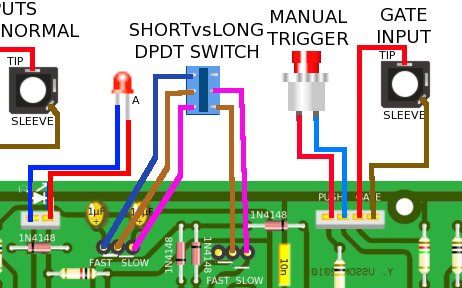 |
|
|
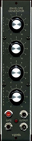
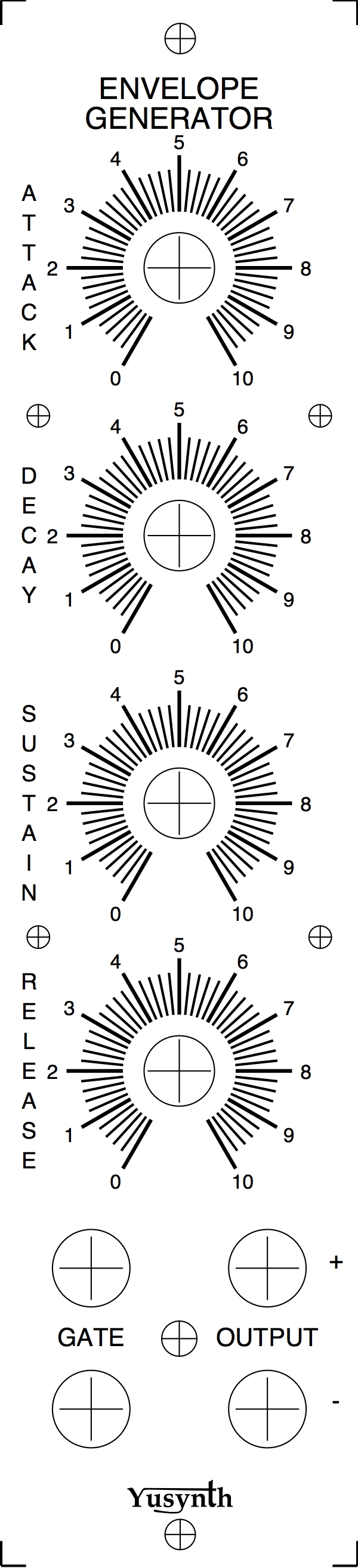
| Front panel |
|||
|
|
|
Settings and trimming
|
| This circuit does not require any trimming. |
|
|
References |
|
|
|||
|
|


