Modified : march 12th 2017

Mixout-VC Panner

En français
back to summary


Description

This module is the combination of two utility modules :
  • the first utility is a quadruple VC-PANNER (and mixer, though not VC )
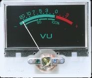
  • the second utility is an output module providing master volume control, tonality control and old-school vu-meters as well as a monitoring output for headphones.
I designed separate PCBs for these sub-modules, therefore it is possible to use  either the VC-panner or the output  monitor sub-modules on their own.


Schematics


QUAD VC-PANNER & MIXER


OUTPUT & MONITOR STAGE

This sub module is based on very classical circuits that can be found in many electronics textbooks.
For one channel and from left to right :
  • a classical baxandall tonality filter, with both cut & boost for treble and bass, it is build around two OPA (U1a,d)
  • a line output buffer based on a classical buffer inverter (U3b)
  • a level display, based on a single OPA amplifier and a rectifier bridge (D5,D6,R28,R29) and an oldschool analogue panel vu-meter connected betwen the diodes,
  • and a headphone amplifier stage (based on the Yamaha CS15 circuit) using a single OPA combined with a complementary pair of transistors providing enough current to drive a HiFi stereo headset.

Printed Circuit Board and Component Layout

VC-Panner submodule
PCB designs


Layouts


Download the Quad VC-Panner schematic as a PDF file

Download theQuad VC-Panner PCB as a PDF file

WARNING ! The document is formatted to be printed directly on a mylar for photo-etching or a "press & peel" paper. Make sure that when the printed face of mylar is in contact with the copper side of the PCB, the lettering can be read normally.
Output & Monitor sub module
PCB designs


Layouts


Download the Output & Monitor schematic as a PDF file

Download the Output & Monitor PCB as a PDF file

WARNING ! The document is formatted to be printed directly on a mylar for photo-etching or a "press & peel" paper. Make sure that when the printed face of mylar is in contact with the copper side of the PCB, the lettering can be read normally.


MOTM PSU version
Solder a strap wire between the negative solder pads of the DOTCOM imprint and the Eurorack imprint

EURORACK PSU version
Solder a strap wire between the negative solder pads of the DOTCOM imprint and the MOTM imprint


List of parts and building instructions

QUAD VC-PANNER & MIXER
All resistors are 1% (1/4W to 0.6W) unless specified otherwise
Trannies are to be matched by pairs (Q101/Q102),(Q201/Q202)...
Color black is used for components belonging to the common part of the circuit, colors red, blue, green, brown are used to discriminate the components as a function of the channel they belong.
reference
value
number
U5,
U102,
U202,
U302,
U402
TL072
5
U101,
U201,
U301,
U401
TL074
4
U103,
U203,
U303,
U403
LM13700 or NJM13700
4
Q101,Q102,
Q201,Q202,
Q301,Q302,
Q401,Q402
BC557B (final B is important !)
8
R1,R2
10
2
R125,R126,R133,R134,
R225,R226,R233,R234,
R325,R326,R333,R334,
R425,R426,R433,R434
100
16
R109,R121,
R209,R221,
R309,R321,
R409,R421
2.2K
8
R108,R120,R124,R129,R132,R137,
R208,R220,R224,R229,R232,R237,
R308,R320,R324,R329,R332,R337,
R408,R420,R424,R429,R432,R437
10K
24
R127,R135,
R227,R235,
R327,R335,
R427,R435
15K
8
R3,R4 27K for +15V/-15V PSU, 12K for +12V/-12V PSU
2
R122,R123,
R222,R223,
R322,R323,
R422,R423,
27K
8
R128,R136,
R228,R236,
R328,R336,
R428,R436
33K
8
R5,R6
47K
2
R104,R130,R138,
R204,R230,R238,
R304,R330,R338,
R404,R430,R438
100K
12
R105,R106,
R205,R206,
R305,R306,
R405,R406
150K
8
R102,R103,
R202,R203,
R302,R303,
R402,R403
200K
8
R101,
R201,
R301,
R401
330K
4
R131,
R231,
R331,
R431
1M
4
T101
T201
T301
T401
50K 1 turn mini-trimmer
8
P101,P102,
P201,P202,
P301,P302,
P401,P402
100K LIN pannel potentiometer
8
P103,
P203,
P303,
P403
200K or 220K or 250K LOG pannel potentiometer 4
C104,C105,
C204,C205
,
C304,C307
,
C404,C407

100n ceramic multilayer
8
C1,C2
22µF/35V polarized
2
C102,C103,
C202,C203,
C302,C303,
C402,C403
47µF/50V polarized
8
C101,
C201,
C301,
C401
47µF/50V non-polarized
4
Jk101,Jk102,
Jk201,Jk202,
Jk301,Jk302,
Jk401,Jk402
6,5 mm jack socket
8

OUTPUT & MONITOR STAGE
All resistors are 1% (1/4W to 0.6W) unless specified otherwise
reference
value
number
U3
TL072
1
U1,U2
TL074
2
Q1,Q2
BC327
2
Q3,Q7
BC337
2
D1,D2,D3,D4,D5,D6,D7,D8
1N4148
8
R1,R2
10
2
R35,R40
82 1/2W
2
R33,R34,R38,R3ç
150 1/2W
4
R16,R30
1K
2
R7,R21
3.3K
2
R12,R13,R26,R27
4.7K
4
R5,R6,R8,R19,R20,R22
10K
6
R15,R16,R20,R21,R26,R31
22K
6
R11,R25
68K
2
R3,R4,R14,R15,R17,R18,R28,R29
120K
8
R9,R23
220K
2
C3,C6,C13,C16
3.3n
4
C4,C5,C14,C15 33n
4
C8,C18
220n
2
C13,C23
10µF/35V
2
C1,C2
22µF/50V
2
C7,C17
22µF/50V non-polarized (preferred but not critical)
2
P13a,b
10K to 50K log (audio) dual gang
1
P14a,b;P15a,b
100K linear dual gang
2
P16a,b
100K log (audio) dual gang
1
T1,T2
10K 1 turn mini trimmer
2
V1,V2
MONACOR V-22,Panel meter,  55x48 mm, with VU lettering, 250µA/750Ω, ±10%, ref. number: 29.1050
2
Jk1,Jk2
6,5 mm jack socket
2
Jk3
6,5 mm stereo jack socket 1

 
Panel VU-METER : the model I am using can be found in various places, the best way is to contact MONACOR and ask them for their dealer the nearest to you, here is the link to the MONACOR site

Wiring

QUAD VC-PANNER & MIXER
OUTPUT & MONITOR STAGE


Front plate
Panel design


Download the silkscreen mask as a PDF file 


Download the silkscreen mask as a  JPEG file 


Trimming


VC-Panner
The trimmers T101 to T104 are used to adjust the midrange for the paning for each channel.
Basically, for each channel :
  • use a voltmeter and adjust the trimmer in order to measure -4V on the wiper pad of the trimmer (normally you are very close from the optimal setting)
  • Then send a TRIANGLE WAVE(1kHz) with an amplitude of 10Vpp (-5V/+5V) on the input of the channel.
  • Set the PAN LEVEL pot to 0, and the PAN pot to 12 o'clock.
  • Connect a dual channel oscilloscope at the outputs. You should obtain the triangle with equal amplitude on both channels, then turn the PAN pot from Clockwise to Counter-clockwise position : you should observe the disappearing of the triangle on one side and the increase in amplitude on the other side.
  • Now, adjust the trimmers such that when the PAN pot is at 12 o'clock, the amplitude of the two triangle waves is roughly half of that can be measured for one wave when the PAN pot is set to clock-wise or anti-clockwise positions. (If you don't have an oscilloscope by ear using hadphones, check for an even balance at 12 o'clock, then verify that the panning effect acts as expected when rotating the PAN pot).
Output monitor
Set all channels to zero except channel 1, set the TREBLE and BASS pots to 12 o'clock.
Then send a SINEWAVE wave (1kHz) with an amplitude of 10Vpp (-5V/+5V) on the input of  channel1.
  • Set the PAN LEVEL pot to 0, and the PAN pot to 12 o'clock.
  • Set the level pot of channel 1 to 10
  • Set the Master Level pot to 7 (you may use another tick mark if you wish)
  • Adjust the trimmers T1 and T2 such that the Vu-meters reaches the -12dB mark (this way when sending the maximum signal level on all the four channels at the same time you get 0dB on the Vu-meters


The DIY builders' gallery
Here are the photographs of the yusynth ARP modules built by other synth geeks around the world.
Thank you  guys for sending me these nice photos.


Name : sduck
Modular project :
Location : Nashville, USA
Website :

Name : kkissinger
Modular project :
Location : Kansas City, USA
Website :http://kevinkissinger.com

-


back to summary