| Update : june 15, 2006 | Mixer - 1U variant |
En français
 |
 |
back to summary |
 |
 |
| Description |
| Update : june 15, 2006 | Mixer - 1U variant |
En français
|
|
back to summary |
|
|
| Description |
|
|
|
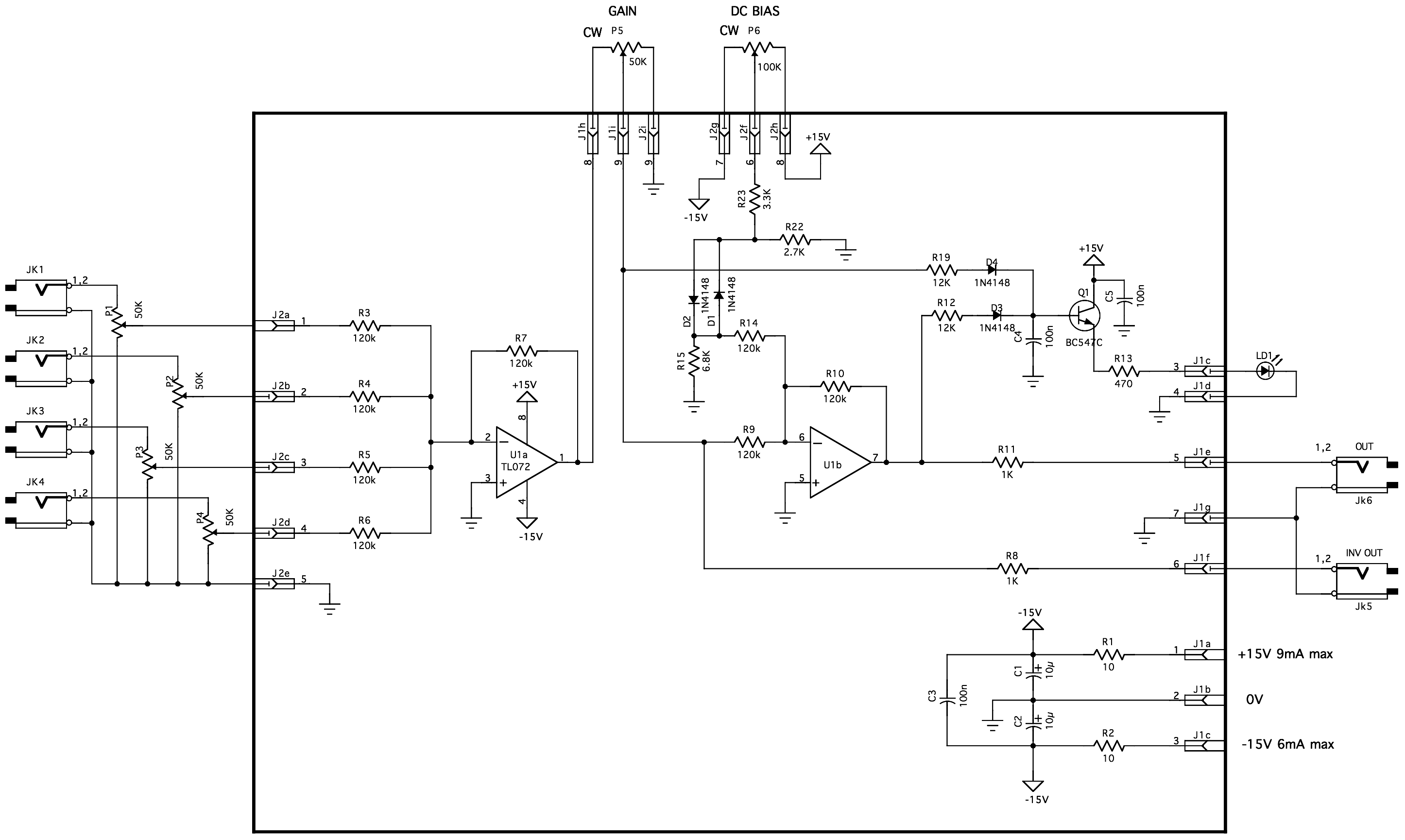
Schematic diagram
|
|
|
|
|
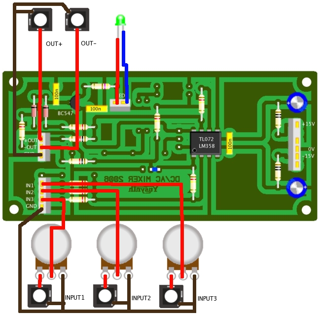
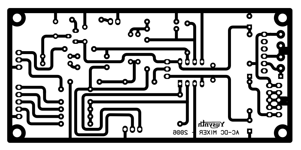
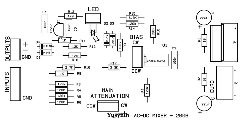
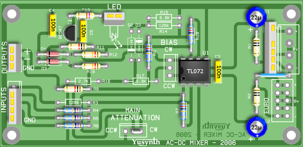
Building instructions
|
||||||||||||||||||||||||||||||||||||||||||
|
||||||||||||||||||||||||||||||||||||||||||
| |
||||||||||||||||||||||||||||||||||||||||||
| Wiring | ||||||||||||||||||||||||||||||||||||||||||
 |
|
|
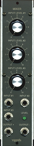
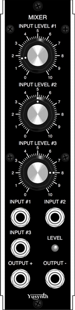
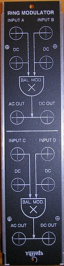
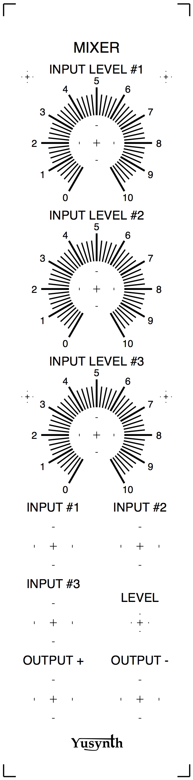
| Front panel |
|||
|
|
|
Settings and trimming
|
| This circuit requires
no trimming and must work straight away. |
|
|
References |
| Any textbook
about OPA should do ! |
|
|||
|
|
