| Modified : october 24th, 2007 |
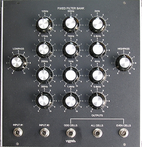
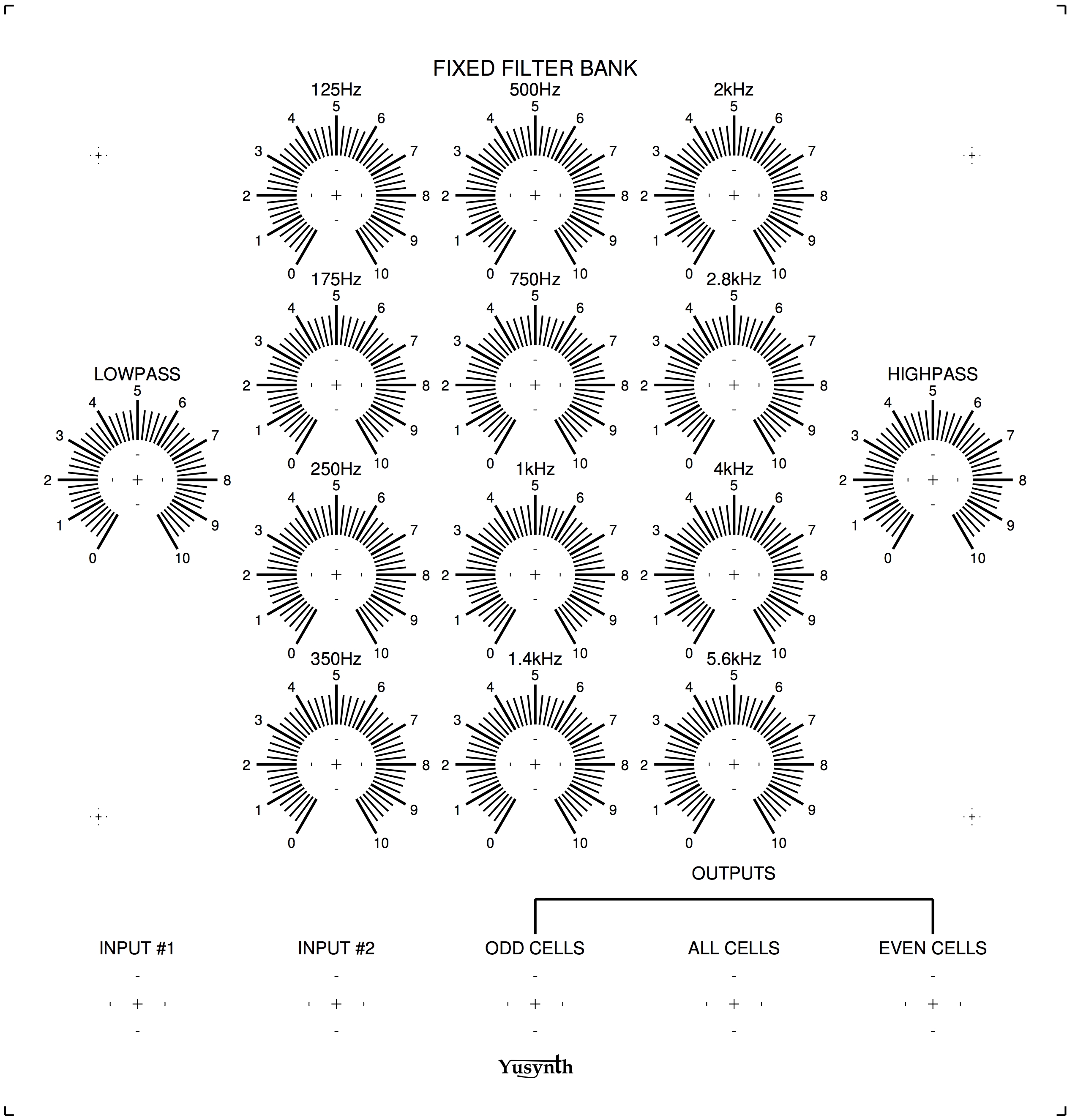
Fixed Filter Bank, FFB
|
En
français
 |
 |
back to summary |
 |
 |
| Description |
| Modified : october 24th, 2007 |
Fixed Filter Bank, FFB
|
En
français
|
|
back to summary |
|
|
| Description |
|
|
|
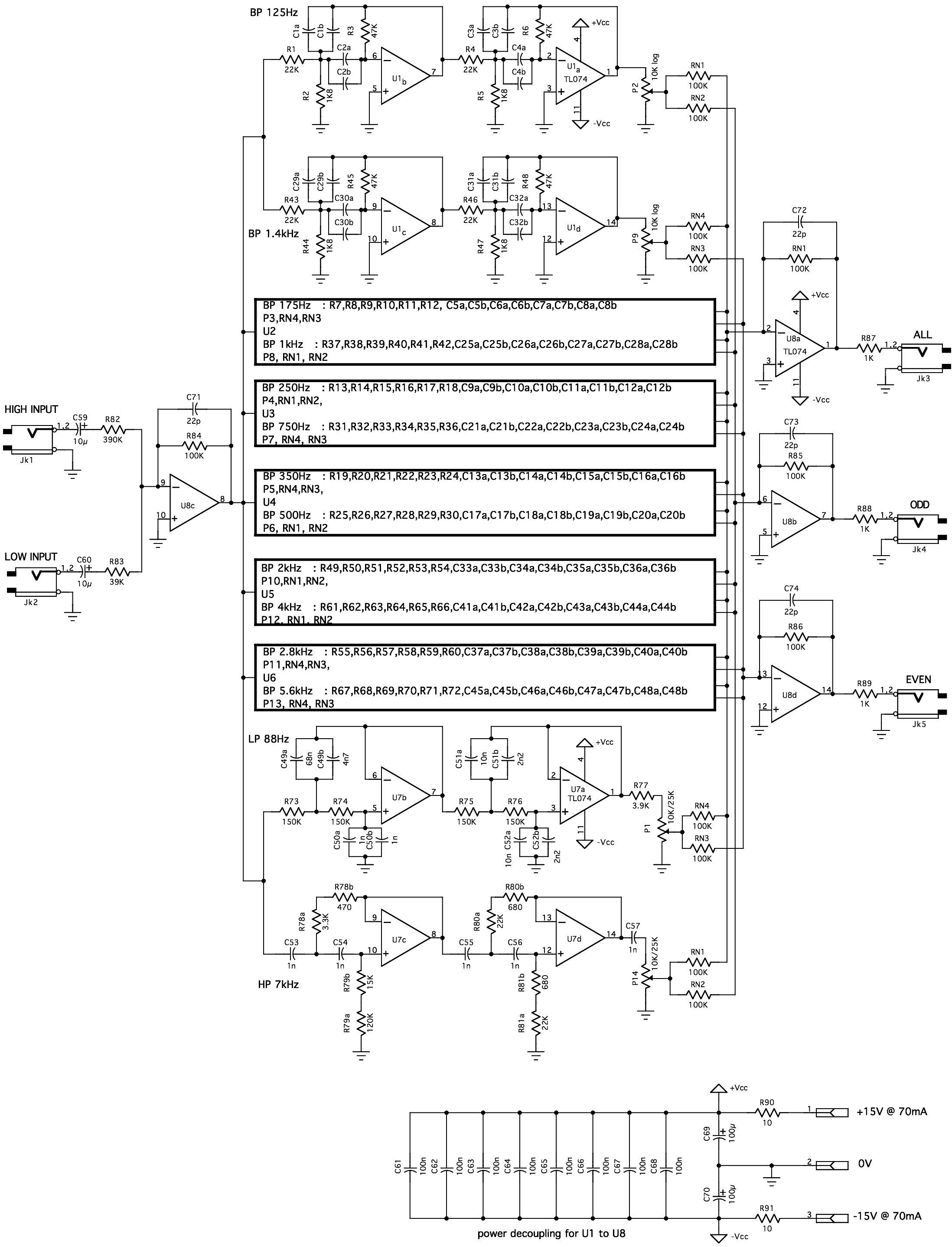
Principle and schematics |
|
A BIT MORE ON FILTER DESIGN
The band-pass cell
In order to obtain steeper
slopes (-12dB/octave) and it is necessary
to chain two Deliyannis 2nd order band-pass cells. I selected fixed
standard values for the resistors giving the expected gain and Q
values and next I calculated capacitor values to obtain the desired
center frequency. However, the capacitor values that are obtained this
way are different from standard capacitor marks. As a matter of fact I
used two capacitors mounted in parallel, this way by adding two
standard
values one obtains a value close to the desired capacitor value (see
the list of cap
values
below). The actual schematic for a band-pass cell is :
|
||||
The
low-pass cell
In order to obtain a steeper
low-pass slope
(-24dB/octave) it is necessary to chain two 2nd order low-pass
cells. In order to increase Q the capacitors of the first cell are set
to different values. Therefore, the actual schematic for a 4th order
resonant low-pass cell is :
|
||||
The
high-pass cell
In order to obtain a steeper
high-pass slopes
(-24dB/octave) it is necessary to chain two 2nd order high-pass
cells. In order to increase Q the resistors of the first cell are set
to different values. Therefore, the actual schematic for a 4th order
resonant high-pass cell is :
|
||||
 |
||||
|
|
|
|
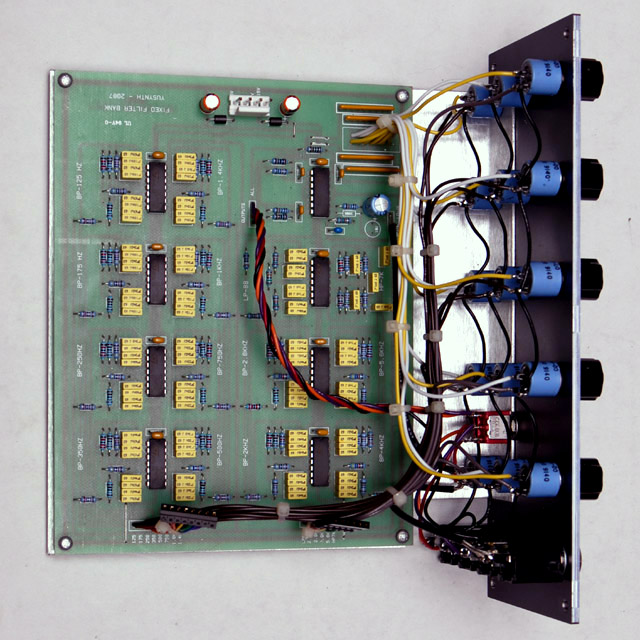
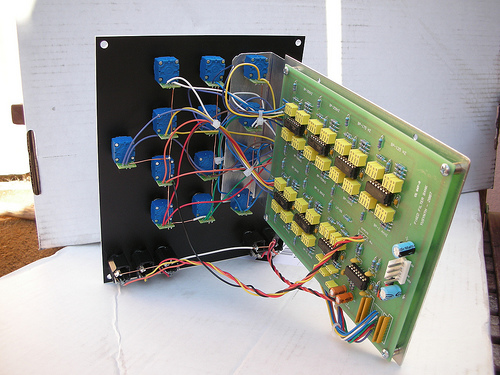
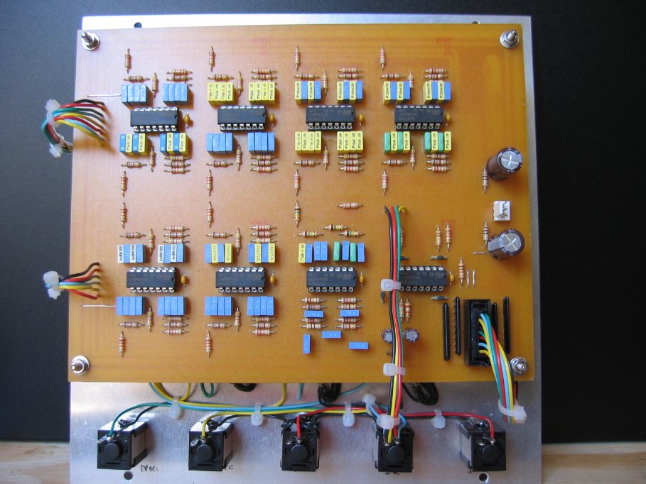
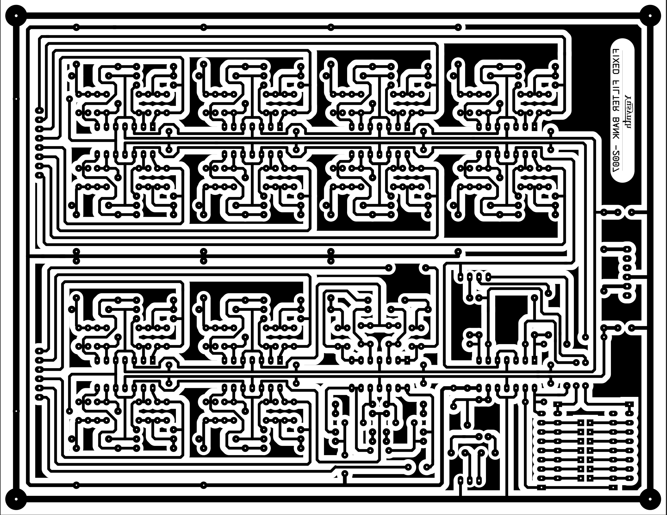
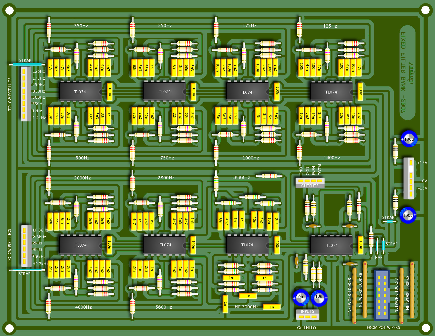
Printed Circuit Board and Component LayoutNOTE : the PCB and a component kit for this module are now made available by Bridechamber |
|||
|
|
|
List of parts and building instructions
|
||||||||||||||||||||||||||||||||||||||||||||||||||||||||||||||||||||||||||||||||||||||||||||||||||||||||||||||||||
|
||||||||||||||||||||||||||||||||||||||||||||||||||||||||||||||||||||||||||||||||||||||||||||||||||||||||||||||||||
|
||||||||||||||||||||||||||||||||||||||||||||||||||||||||||||||||||||||||||||||||||||||||||||||||||||||||||||||||||
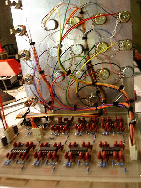
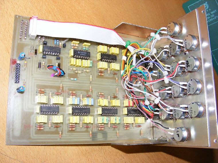
| Wiring |
||||||||||||||||||||||||||||||||||||||||||||||||||||||||||||||||||||||||||||||||||||||||||||||||||||||||||||||||||
Because of the high wire density, I
had to split the wiring diagram into two parts.
|
|
|
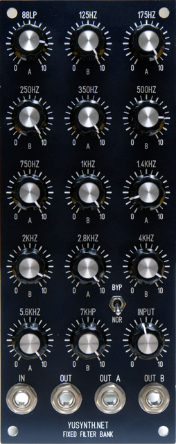
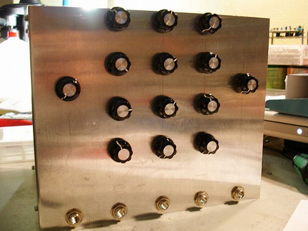
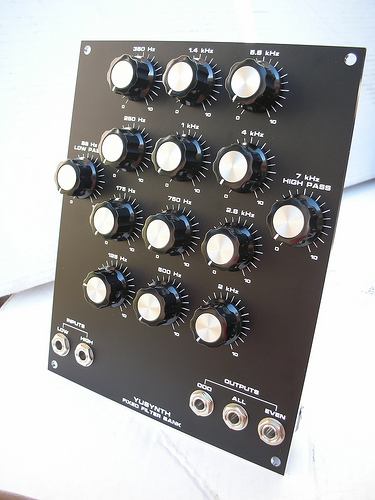
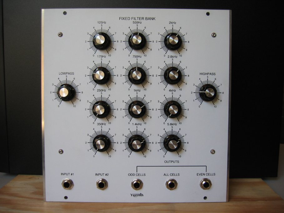
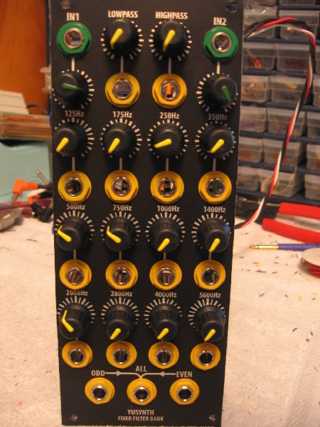
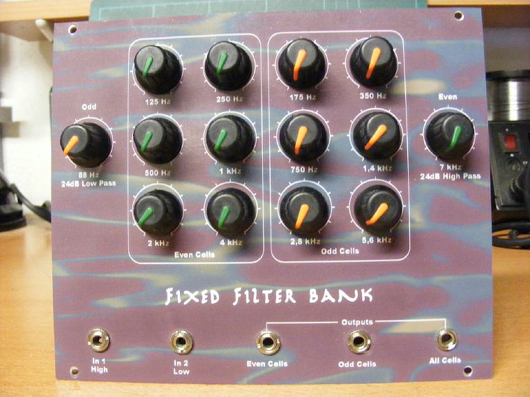
| Front plate |
||
|
|
|
Measurements |
|
| Below are some spectrum measurements made on the prototype. The measurements were obtained using a "white" noise source and measured with the SignalScope software (evaluation version, on Macintosh MacOSX) |
 |
 |
 |
 |
 |
| White noise reference signal | Low-pass 88Hz | Band-pass 350Hz | Band-pass 1kHz | High-pass 7kHz |
 |
 |
 |
 |
 |
| LP
88Hz
+
HP
7kHz |
All
BP |
All |
BP-odd
(red)
BP-even
(green) |
BP-odd+HP(red) BP-even+LP(green) |
|
|
 |
 |
  |
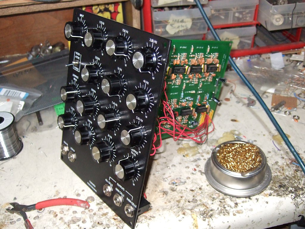
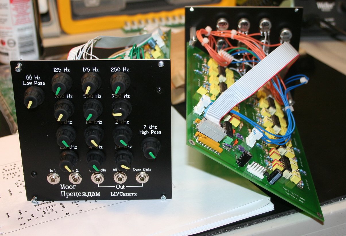
| Name
: David Brown Modular project : Modularsynthesis.com Location : USA Website : www.modularsynthesis.com/yusynth/ffb.htm |
Name
: Alison project Modular project : Alison project Location : Winnipeg, Canada Website : www.thealisonproject.com |
Name
: Tobias Schilly
Modular project : funk machine Location : Germany Website : www.mdz.de, www.myspace.com/schrumpfschlauch |
  |
 |
 |
| Name
: DJthomaswhite Modular project : Location : USA Website : naturalrhythmmusic |
Name
: Dave Wright Modular project : Notbreathing Location : USA Website :www.notbreathing.com |
Name
: Julien Modular project : Location : France Website : |
  |
 |
 |
| Name
: Zarko Modular project : Location : Gardanne, France Website : |
Name
: David Ingebretsen Modular project : Digembre Location : Salt Lake City, USA Website : digembre |
Name
: Newandrewthal Modular project : Location : USA Website : |
  |
  |
|
| Name
: Baronrouge Modular project : Location : France Website : |
Name
: Kevin Kissinger Modular project : Location : Kansas City, Mo USA Website : |
|
|||
|
|

