|
The VCOs of the Wildcat synth are inspired
from
the design of the Moog Minisonic monosynth. I had to deal with two
problems
with these. the first problem came from the PCB rev1 that required some
track modifications (these errors have been corrected in the rev2 PCB,
thanks Tom!) The second problem came from the original design of the
VCOs by Moog
(BTW who am I to criticize Moog's designs...  ).
The output waveforms are far from being pure : when looking at these
with
a good old analogue oscilloscope (not a software + audio card!) one
can
see unwanted spikes on the sawtooth waveform, a not so triangular
waveshape,
an unbalanced square wave and a very dirty sinewave! I modified the
value
of some components, added new ones, removed some in order to obtain
better
waveshapes. ).
The output waveforms are far from being pure : when looking at these
with
a good old analogue oscilloscope (not a software + audio card!) one
can
see unwanted spikes on the sawtooth waveform, a not so triangular
waveshape,
an unbalanced square wave and a very dirty sinewave! I modified the
value
of some components, added new ones, removed some in order to obtain
better
waveshapes.
Improving the waveshapes is not mandatory ! If you wish to have the
genuine Minisonic sound don't change nothing ! It is clear that the
unmodified
VCOs provide interesting waveshapes that are sufficient for making
electronic
music. However, some ultrasonic components that are present in the
sinewave
of the VCO will produce very unpredictable effects when fed to the ring
modulator for instance. This is an old debate on what is to be
considered
as an interesting feature or as a design blunder...
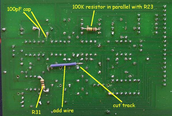
This is the modified schematic of the VCOs, the changes are :
- R20 is changed from 75k to 51k (Tom Gamble changed it to
60k) in order
to make the triangle signal more symmetrical;
- R23 is changed from 10k to 9k (in my case I simply solder a
100k in
parallel
with the existing 10k resistor) in order to obtain a triangular
waveshape
ranging from -2.8V to +2.8V;
- R27 must be removed and R26 changed to 78k in order to
improve the
pulse
width range of the squarewave;
- R31 must be disconnected from the 6 volts reference voltage
(common
point
between C5,R18,Q1,Q2,R19 and R23). This suppress a parisitic spike
visible
on the slope of the sawtooth signal that is due to the current draw by
the open collector output of the U4 comparator;
- R36 must be lowered from 1k to 845 ohms in order to reduce
the
proportion
of odd overtones in the sine waveshape.
- A 100 pF capacitor must be inserted in parallel to R39 in
order to
cancel
out an ultrasonic (1MHz) damping oscillation superimposed to the
sinewave.
Enhancement of the triangle waveshape
click to enlarge
|
click to enlarge
|
|
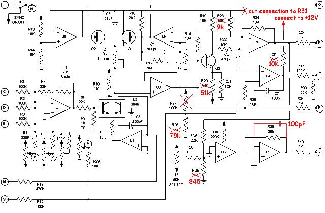
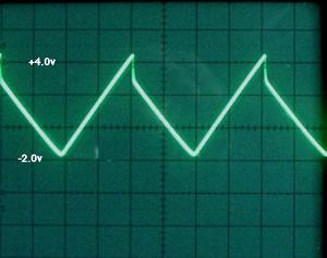
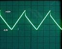
On the original circuit, the triangle
waveshape is not symmetrical. This is due to a bias in the polarisation
of the emitter of transistor Q3. Because the emitter is not negative
enough,
a steep step arises at the junction of the rising slope and of the
decrease
slope.
|
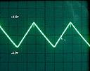
By lowering the value of R20,
the emitter of Q3 is made more negative. It removes the step. Changing
the value of R23 to a slightly lower one makes it possible to have a
triangle
perfectly balanced between -2.8V and +2.8V
|
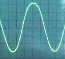
Enhancement of the sinewave
|
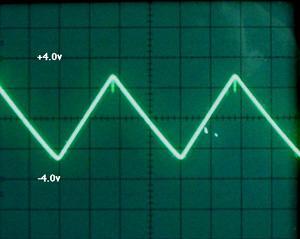
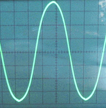
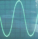
Sinewave at 1000 Hz
|
|

click to enlarge
|
click to enlarge
|
|
This scope image illustrates the
shape of the sinewave at a frequency of 1kHz after applying the mods to
make the triangle waveshape symmetrical and lowering the value of R36
to
845 ohms to reduce the amount of odd overtones. The sinewave looks
quite
good but a small spike is visible on the negative crests (white
arrows).
In fact, when using a faster scope sweep the spike appears as a damping
sine with a frequency around 1MHz !
|
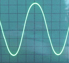
Adding a 100pF capacitor in parallel
to R39 filters out the spikes and the sinewave looks very nice now and
sounds very mellow too!...
|
|
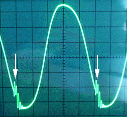
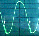
Sinewave at 18 500 Hz
|
|
click to enlarge
|
click to enlarge
|
|
This scope image illustrates the
shape of the sinewave at a frequency of 18.5kHz after applying the mods
to make the triangle waveshape symmetrical and lowering the value of
R36
to 845 ohms to reduce the amount of odd overtones. The sine looks very
dissymmetrical and the ultrasonic wave puffs are quite obvious (white
arrows).
|
The effect of the 100pF capacitor
is very dramatic ! The ultrasonic waves are completely removed.
However,
the sine remains slightly unbalanced but this is quite bearable.
|
PCB mods
|