VCAs |
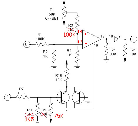
The VCAs of the Wildcat are quite classical in design. In the original schematic the VCA are connected in non-inverting mode; However, the PCB layout is the VCAs are in the inverting mode! Tom Gamble made some corrections to his original circuit, he suggested to change R3 from 1M to 100K. However, I noted that for all the four VCAs of the board, I could hear a noticeable bleedthrough of the signal when the CV input was set to 0V (which is supposed to completely silence the signal). The maximum rejection level was -45dB which is quite poor. I tried to change the values of some of the resistors of the CV circuit and came up with the following values : R8 must be increased to 1K5 and R9 reduced to 75K. With these new values no signal bleedthrough can be heard ! The total dynamics become something like 70 to 75dB which is quite satisfactory. Still this design is far from being ideal and there is some bias voltage at the output ! For audio signal you may add a 10µF cap at the output. |
 |