|
The original design of the
S&H circuit suffers from some quirks.
Tom Gamble made some modifications (see Wildcat rev 2 schemo) such as
removing
R4. As a matter of fact, this resistor introduces a lot of droop and
the circuit
cannot hold the voltage for a long time. Personally, I also bypassed
R3, in
order to get a faster voltage tracking during the sampling phase.
Another point was bothering me : the original
circuit behaves more like a Track & Hold circuit rather than a
Sample
and Hold circuit ! To have it behaving the way I expected, I made the
following
mods : remove R5 and insert a 15nF cap at the clock input. This
capacitor
acts as a differentiator with a short time constant : therefore the
sampling
time will remain rather short (around 10ms).
There is also an error in the pin label for the output of the module :
the actual output pin is D and not C as it was stated in the original
schematic (Rev1 and Rev2).
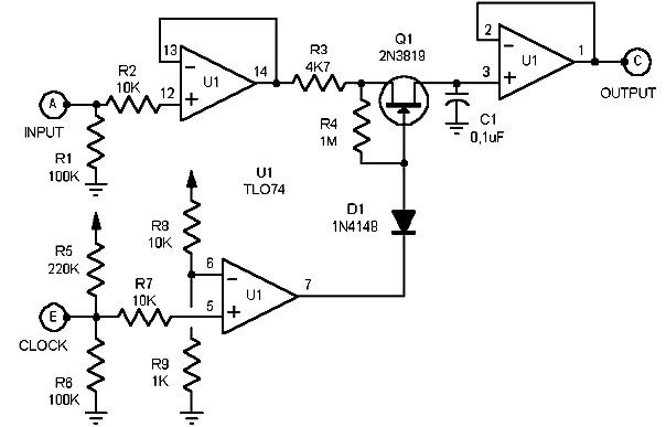
original schematic (copyright EFM)
|
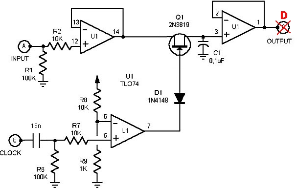
modified schematic
|
|