|
The
Ring Modulator of the Wildcat is based on an old design by Tom Gamble
tusing a CA3046 transistor array to form a Gilbert balanced modulator.
Instead of the CA3046, the Wildcat uses a very efficient and classical
balanced modulator IC (MC1496). However, the result is far from being
convincing : high amount of distorsion and poor carrier and modulation
nulling. In order to improve the circuit, I studied the datasheet of
the MC1496. There, it is stated that the input levels must be limited
to 300 mVpp to reduce the amount of distorsion. Thus my first
modification was to add 100k resitors in series with the input
capacitors (as a matter of fact these two resistor cannot be inserted
on the PCB, these will have to be directly soldered to the input plugs.
This way, if you feed the Ring modulator with the sine
signals of the Wildcat's VCOs, the level is limited to 130 mVrms at
pins 8 and 4. However, with such a limitation the output level of the
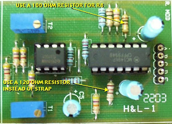
module remains really low. To increase the output level, I changed the
value of R8. This resistor sets the gain in the MC1496. I selected a
value of 100 ohms that provides the highest gain while limiting the
distorsion amount. A smaller value introduces too much distorsion.
Next is the poor rejection of the carrier and modulation signals. As a
matter of fact, both the positive and negative inputs (pins 1 & 4,
pins 8 & 10) must be polarized. In Tom's design the signal inputs
(pins 4 & 8) are missing such a polarization. Therefore, I have
added some polarization resistors to pins 4 and 8. A 120 ohm resistor
connects pin 8 to the wiper of T1, and a 10k resistor connects pin 4 to
the wiper of T2. I also inserted a 120 resistor between pin 10 and the
wiper of T2.
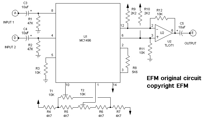
original schematic (copyright EFM)
|
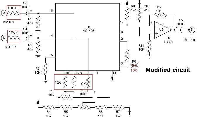
modified schematic
|
Next
are some clues on how to set up the two trimmers T1 and T2. You need an
oscilloscope and spectrum analyzer. Basically you may connect the
output of the ring modulator to the signal input of a PC and use a dual
channel
oscilloscope + spectrum analyzer software (there are some freewares and
sharewares offering these functions).
Here is how to proceed :
- Feed input A with a 1kHz sinewave with a 7Vpp level
(signal from VCO1). Adjust T1 & T2 , alternatively in order to
minimize the output signal (few mV). You can do it also by ear,
adjust T1 & T2 to mute the output signal.
- Disconnect the sine wave signal from input A and
connect it to input B. Re-adjust T1 & T2 in order to
minimize the output signal.
- Repeat points 1 and 2, until achieving the lowest
bleedthrough...
Then connect a 1kHz sinewave from VCO1 to input A and a 1.55kHz
sinewave from VCO2 to input B. Connect the output to the audio signal
input of a PC, and observe the obtained spectrum. You should observe
the spectra below depending of the trimmers settings.
Once you have obtained the second spectrum, your ring modulator is
nearly trimmed !
A last trimming will complete the procedure. For this you need a good
sinewave generator with a low harmonic distorsion. This means that,
definitely, you cannot use the sinewave signal from one the Wildcat's
VCOs. Once you have found this pure sinwave generator, set its
frequency to 1kHz and its amplitude to 2Vpp. Now, connect this sine
signal to both inputs of the Ring Modulator. Then connect the output of
the Ring Modulator to the first channel of your oscilloscope. Connect
the output of the sinewave generator to the second channel of your
oscilloscope. There you must see a 1kHz sinewave on channel two and a
somehow dissymmetrical 2 kHz sinewave. Now, you must
slightly adjust T1 and T2 in order to obtain a perfectly symmetric
2kHz sinewave. That's it !
|
|
|
Unbalanced modulation spectrum
The
spectrum on the left shows a typical unbalanced setting. The carrier
and modulation signals (1kHz and 1.5kHz) are not correctly rejected.
They are 20dB above the generated sum and differences signals also
called sidebands (C-M :
1500-1000->500Hz; C+M : 1500+1000->2500Hz). The other peaks are
overtones created by the harmonic distorsion. If you see this, adjust
T1 & T2, in order to decrease M and C, and increase (C-M) and (C+M).
|
click to view more
|
Balanced modulation spectrum
The spectrum on the left
shows a
typical balanced setting. The carrier and modulation signals (1kHz
and 1.50kHz) highly reduced. They are 35 to 45dB below the
generated sum and differences signals (C-M : 1500-1000->500Hz; C+M :
1500+1000->2500Hz). The other peaks are overtones created by the
harmonic distorsion. If you see this, that's it you're done with the
settings !
|
click to magnify
|
When
optimal carrier and modulation nulling is achieved, the output of the
module looks like shown on the left with a 1kHz and a 1.55kHz input
signals.
|
click to magnify
|
The
same with a 150Hz and a 1.55kHz input signals
|
|