| Updated : nov. 27, 2007 | Steiner VCF |
En
français
 |
 |
back to summary |
 |
 |
| Description |
| Updated : nov. 27, 2007 | Steiner VCF |
En
français
|
|
back to summary |
|
|
| Description |
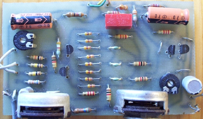
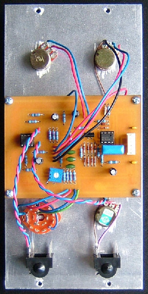
Below,
is a picture of one out
of the three Steiner VCF I built in 1979. The PCB was hand drawn with
an etch resistant pen. Those three guys are still alive and kicking !
By the way, the transistors are BC547 (NPNs) and BC557 (PNP).
|
||||||||||||
 |
||||||||||||
How does this simple basic filter
sound ? Well, great I'd say !
Following are two sound clips (mp3) excerpted from improvisations I
played back in 1980 with my US1
modular.

Next are audio examples for the prototype based on a 2SC1583 and an OPA. The CA3096 version sounds exactly the same.
|
|
|
Schematics |
 |
|
This version works nicely
and sounds exactly the same as the traditional circuit based on
discrete components. For this version, I use a dual OPA (TL072) one as
an input buffer, the second to level up the output signal. By the way,
both are inverting amplifier, thus the output signal is not inverted
with respect to the input signal.
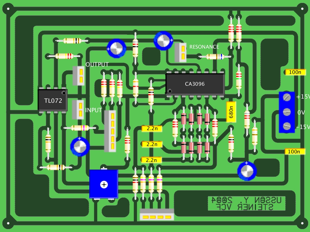
The core of the filter is based on a low cost transistor array, the CA3096. Why did I choose such an array ? Well, simply because I have something like twenty of these sleeping in a drawer of mine. If you cannot find it (I think it's obsolete now) you can replace it by an Intersil HFA3096 that is pin to pin compatible and costs around US$2.20. When T1 is properly adjusted, the filter tracks in V/octave over a four octave range, above and below this range the tracking is no longer linear. |
 |
|
This version works and
sounds also very nice. In my first attempt, it did not work properly
due to
an error of mine : I used a 22k for R12. As a matter of fact, 22k was
too small and
lowered to much the input impedance of the OPA. Osamu Hoshuyama found
the bug and suggested that the value of R12 must be significantly
increased (e.g. 2M2). I did it and it fixed everything (a big thank to
Osamu
!).
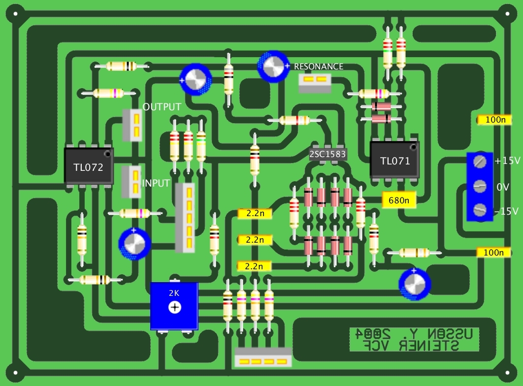
The 2SC1583 dual transitor can be purchased for a reasonable price at AMS ( http://store.americanmicrosemiconductor.com ). or in Europe at Reichelt ( http://www.reichelt.de ) or at BMM ( http://www.bmm-electronics.com ). By the way, if you cannot find 2SC1583 you can use either matched BC547 or matched 2N3904 trannies. If you use the PCB design shown below, you must drill a second hole for the emitter of the second transistor (the emitters in the 2SC1583 use a common pin [3]). I tried with BC547s and it works perfectly. When T1 is properly adjusted, the filter tracks in V/octave over a four octave range, above and below this range the tracking is no longer linear. Besides, I have included a diode limiter (D9/D10) in the feedback loop of the TL071. This makes it possible to limit the amplitude of oscillation of the filter at maximum resonance. This improvement was introduced by Yasunori HIRAKAWA .Well, I guess it's always like that, you think you made an original design and then you discover one year later that somebody else already made it several years before ! While surfing the internet I came accross a site (sorry I didn't bookmark it, I know that's dumb) where I found this schematic of a cheap guitar synthesizer by Terry Tsutsumi which uses the very same filter design : a 2SC1583 dual NPN and a generic OPA ! Since it was designed to operate with a single 9V battery and that some people asked me which modifications had to be applied on my circuit to achieve this, I have decided to make it downloadable. Here it is :  |
|
|
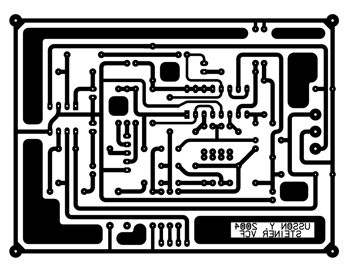
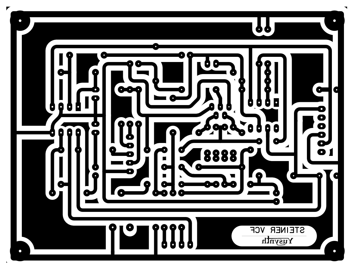
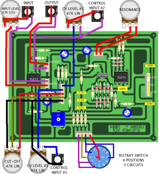
Printed circuit boards and component layouts |
||||||
|
|
|
Building details |
|||||||||||||||||||||||||||||||||||||||||||||||||||||||||||||||||||||||||||||||||
| CA3096 version | |||||||||||||||||||||||||||||||||||||||||||||||||||||||||||||||||||||||||||||||||
|
|||||||||||||||||||||||||||||||||||||||||||||||||||||||||||||||||||||||||||||||||
| 2SC1583 version | |||||||||||||||||||||||||||||||||||||||||||||||||||||||||||||||||||||||||||||||||
|
|||||||||||||||||||||||||||||||||||||||||||||||||||||||||||||||||||||||||||||||||
| Wiring |
|||||||||||||||||||||||||||||||||||||||||||||||||||||||||||||||||||||||||||||||||
 |
|
|
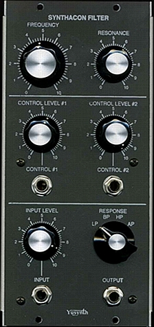
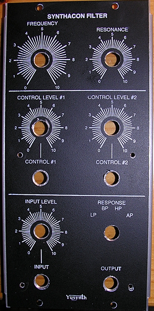
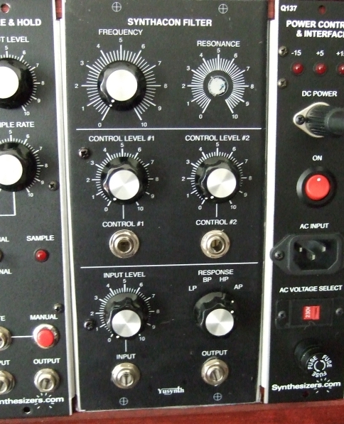
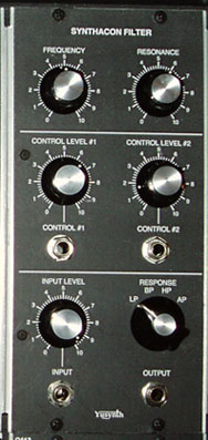
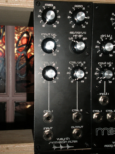
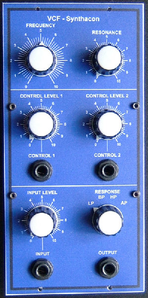
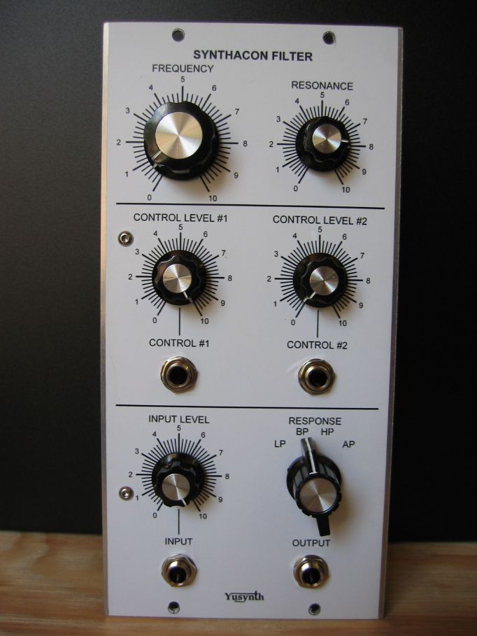
| Front panel |
|||
|
|
|
Trimming |
| Trimming is very easy. Adjust the 2k trimmer in order to obtain a V/octave tracking. |
|
|
References |
||||||||||
Here are interesting links where to
find schematics and infos
about the Steiner VCF :
You can also purchase a
ready
made Steiner VCF at Cyndustries ! |
 |
 |
 |
| Name
: Meic Modular project : Scaff beat Location : Hamburg, Germany Website : http://www.myspace.com/scaffbeat |
Name
: Olivier Abplanalp Modular project : Cave Studio Location : Schaffhausen, Switzerland Website : http://www.cavestudio.ch |
Name
: Patrick
Pseudo : Baronrouge Modular project: JHC live lab Location :Toulon, France Web site : http://myspace.com/patjhc |
 |
  |
 |
| Name
: Julien Pseudo : Modular project: Location: France Web site : |
Name
: Pseudo : Sebo Modular project: Location: France Web site :http://www.cosaquitosenglobo.com.ar |
Name
: Frédéric Monti Pseudo : Zarko Modular project: Location: Gradanne, France Web site : |
|
|||
|
|